Air conditioner
An air-conditioning device and control device technology, applied in air-conditioning systems, high-efficiency regulation technology, space heating and ventilation, etc., can solve the problem of large transmission power and achieve the effect of reducing transmission power
- Summary
- Abstract
- Description
- Claims
- Application Information
AI Technical Summary
Problems solved by technology
Method used
Image
Examples
Embodiment approach 1
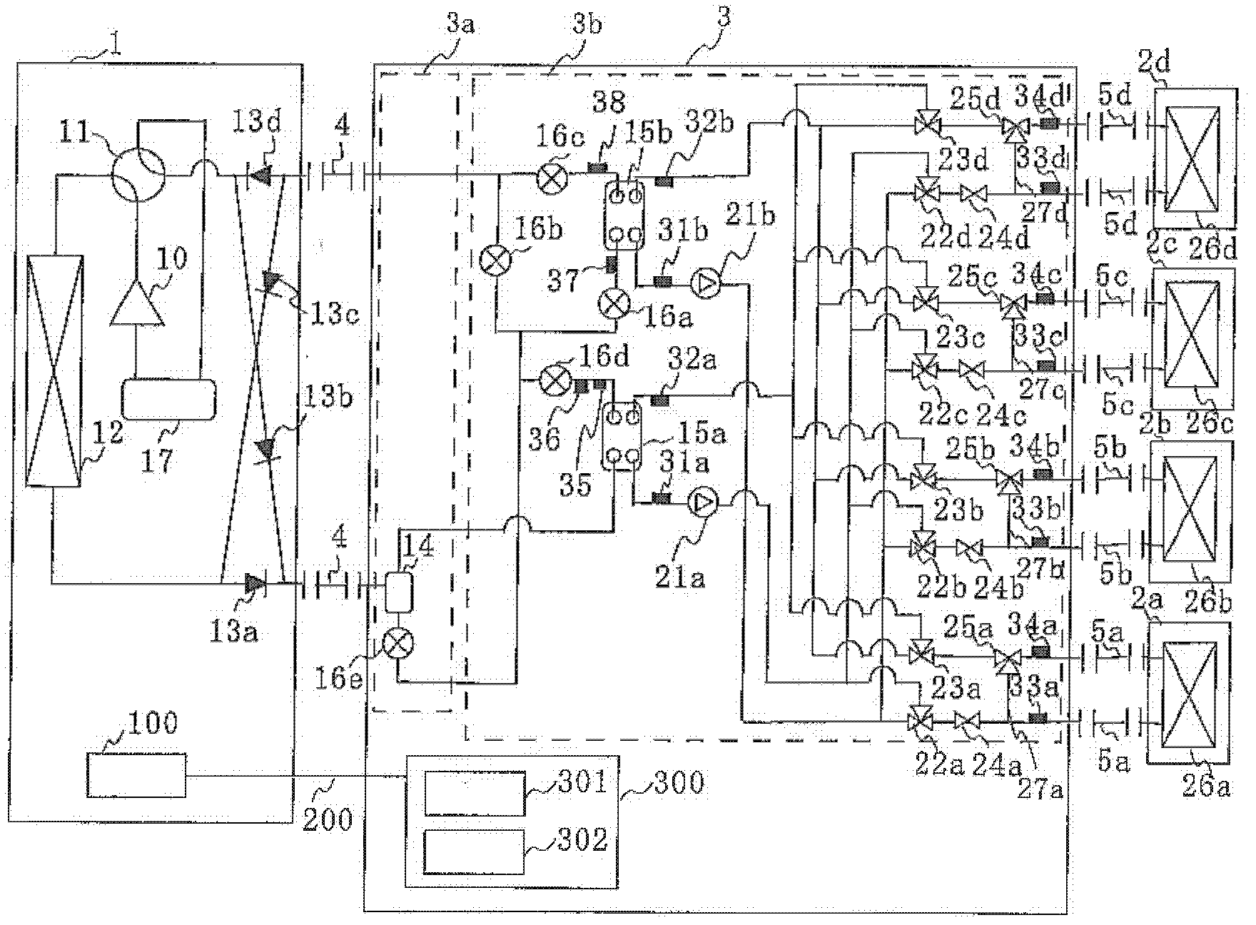
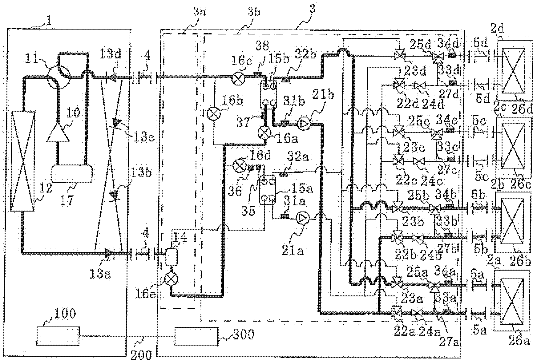
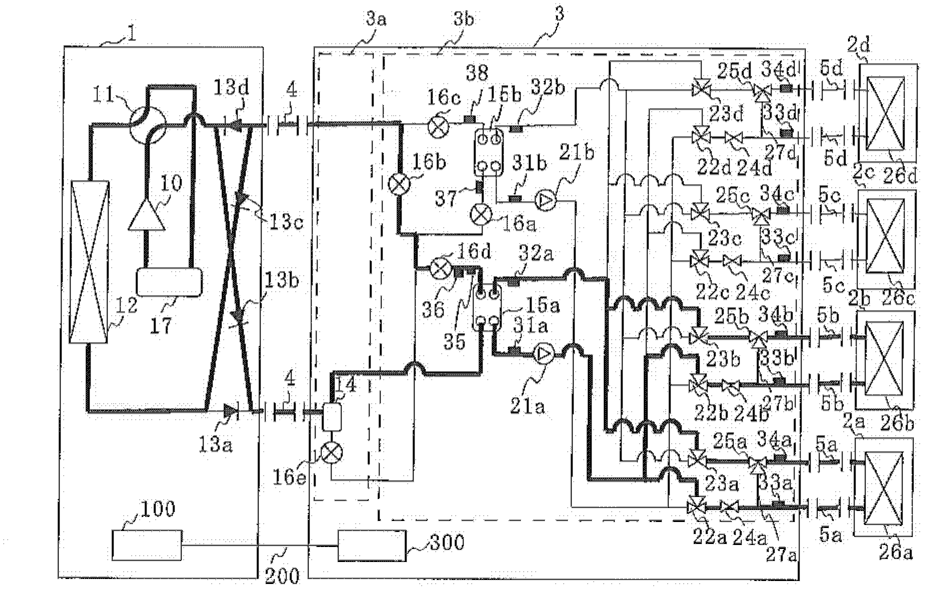
[0025] figure 1 It is a figure which shows the installation example of the air conditioner which concerns on embodiment of this invention. figure 1 The air conditioner has an outdoor unit 1 as a separate unit, one or more indoor units 2, and a relay unit 3, the outdoor unit 1 is used as a heat source device, and the indoor unit 2 performs air conditioning in the air-conditioning target space, The relay unit 3 performs heat exchange between the refrigerant and a heat-transporting medium (hereinafter referred to as heat medium) different from the refrigerant, and relays heat transfer. The outdoor unit 1 and the relay unit 3 are connected by a refrigerant pipe 4 for circulating a refrigerant such as a quasi-azeotropic refrigerant such as R-410A or R-404A to transfer heat. In addition, between the relay unit 3 and the indoor unit 2, in order to circulate heat mediums such as water, water added with non-volatile or low-volatile preservatives within the air-conditioning temperature...
Embodiment approach 2
[0121] Figure 10 It is a figure which shows the structure of the air-conditioning apparatus of Embodiment 2. exist Figure 10 Among them, the flow meters 41 a , 41 b , 41 c , and 41 d detect the flow rates of heat medium flowing into the use-side heat exchangers 26 a to 26 d , respectively, and transmit the signals of the flow values to the relay unit side control device 300 . In this embodiment, for example, by providing the flow meters 41a to 41d, the relay unit side control device 300 can obtain the flow rate value of the heat medium flowing through the use side heat exchangers 26a to 26d. Furthermore, based on the flow rate of the heat medium flowing through the use-side heat exchangers 26a-26d, the detection temperatures of the third temperature sensors 33a-33d, and the detection temperatures of the fourth temperature sensors 34a-34d, the relay unit side control device 300 can The aforementioned (1) formula calculates the heat load of the use side heat exchangers 26a...
Embodiment approach 3
[0130] In the above-mentioned first embodiment, the refrigerant of the quasi-azeotropic mixture refrigerant has been described as the refrigerant circulating in the refrigeration cycle, but the present invention is not limited thereto. Single refrigerants such as R-22 or R-134a, non-azeotropic mixed refrigerants such as R-407C, and CF containing double bonds in the chemical formula can also be used. 3 CF=CH 2 A refrigerant having a relatively small value of the global warming coefficient and a mixed refrigerant containing the refrigerant, CO 2 or natural refrigerants such as propane, etc.
[0131] Furthermore, in the air-conditioning apparatus of the above-mentioned embodiment, the storage unit 17 is provided in the refrigeration cycle, but the storage unit 17 may not be provided, for example. The check valves 13a to 13d are also not an essential mechanism, so even if the refrigeration cycle is configured without using the check valves 13a to 13d, the same operation can be p...
PUM
 Abstract
Description
Claims
Application Information
 - R&D Engineer
- R&D Manager
- IP Professional
- Industry Leading Data Capabilities
- Powerful AI technology
- Patent DNA Extraction
Browse by: Latest US Patents, China's latest patents, Technical Efficacy Thesaurus, Application Domain, Technology Topic, Popular Technical Reports.
© 2024 PatSnap. All rights reserved.Legal|Privacy policy|Modern Slavery Act Transparency Statement|Sitemap|About US| Contact US: help@patsnap.com


