


Quick Research
Generate reliable direction feasibility study reports for your R&D in just a few steps.

Technical Q&A
Discover and master advanced knowledge NOW. Basics, ideas, possibilities, all at once.

Find Solutions
As an expert in R&D theories, this can generate solutions to your technical problems instantly.

Evaluate Feasibility
Analyze your overall solution with one click, know your potential R&D risks in advance.

Monitor Landscape
Get weekly tech updates, stay abreast of the latest tech innovations and key insights.
Data synchronous transmission method for spaced-based routing exchange system, and device and system adopting same
A switching system and data synchronization technology, applied in the field of data processing, can solve problems such as high reliability, difficulty in applying space systems, GPS technology cannot be applied, etc., and achieve the effect of reducing synchronization costs and simplifying synchronization lines
- Summary
- Abstract
- Description
- Claims
- Application Information
AI Technical Summary
Problems solved by technology
Method used
Image

Examples
Embodiment 1
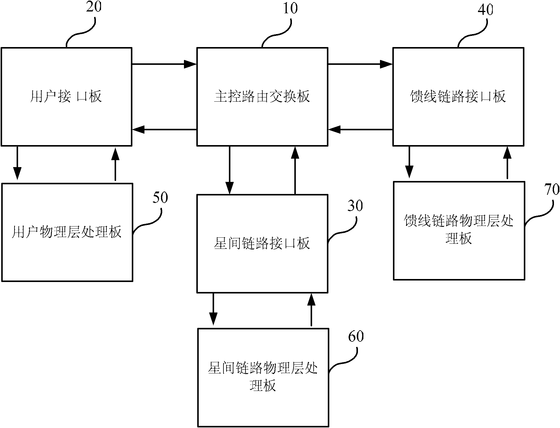
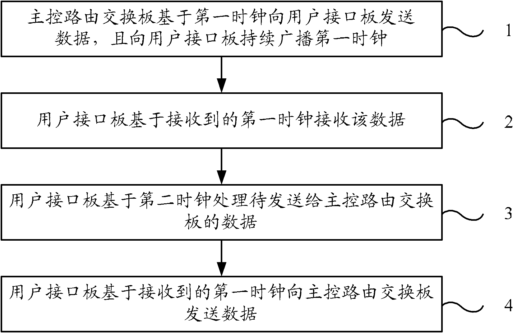
[0048] figure 2 The flow chart of the data synchronous transmission method of the space-based routing and switching system provided by Embodiment 1 of the present invention. The space-based routing and switching system can also be called the on-board routing and switching system. Take the implementation of synchronous transmission between them as an example to illustrate. The typical structure of the on-board routing and switching system is as follows: image 3 As shown, it includes a main control routing switching board 10 , a user interface board 20 , an inter-satellite link interface board 30 and a feeder link interface board 40 . The main control routing switching board 10 realizes data interactive transmission with the user interface board 20 , the inter-satellite link interface board 30 and the feeder link interface board 40 respectively, and completes the routing exchange of various data. The user interface board 20, the inter-satellite link interface board 30 and th...
Embodiment 2
[0059] Figure 4 A schematic structural diagram of a space-based routing and switching system data synchronization transmission device provided in Embodiment 2 of the present invention, the device includes: a clock receiving interface 410 , a clock management module 420 , a data receiving interface 430 , a data processing module 440 and a data sending interface 450 . Wherein, the clock receiving interface 410 is used to receive the first clock continuously broadcast by the broadcasting unit board, and the first clock may be the local clock of the broadcasting unit board; the clock management module 420 is used to provide the first clock received by the clock receiving interface 410 To the data sending interface 450 and the data receiving interface 430, and provide the second clock to the data processing module 440, the second clock can be the local clock of the receiving unit board; the data receiving interface 430 is used to receive the broadcasting unit board based on the fir...
Embodiment 3
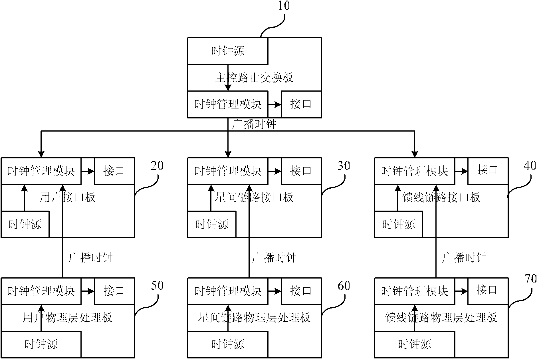
[0065] Figure 5A schematic structural diagram of a space-based routing and switching system provided in Embodiment 3 of the present invention, the routing and switching system includes at least one broadcasting unit board 100 and at least one receiving unit board 200, and each broadcasting unit board 100 and receiving unit board 200 pass through The three data lines are connected. The broadcast unit board 100 includes: a first clock management module 110 , a first data sending interface 120 , a first clock broadcasting interface 130 and a first data receiving interface 140 . Wherein, the first clock management module 110 is configured to provide the first clock to the first data sending interface 120, the first clock broadcasting interface 130 and the first data receiving interface 140, and the first clock may be the local clock of the broadcast unit board 100; The first data transmission interface 120 is used to send data to the receiving unit board 200 based on the first c...
PUM
 Abstract
Description
Claims
Application Information
 - R&D Engineer
- R&D Manager
- IP Professional
- Industry Leading Data Capabilities
- Powerful AI technology
- Patent DNA Extraction
Browse by: Latest US Patents, China's latest patents, Technical Efficacy Thesaurus, Application Domain, Technology Topic, Popular Technical Reports.
© 2024 PatSnap. All rights reserved.Legal|Privacy policy|Modern Slavery Act Transparency Statement|Sitemap|About US| Contact US: help@patsnap.com