
Method for measuring energy of accelerator

An accelerator and energy technology, applied in dosimeters and other directions, can solve the problems of general roughness, rough reference basis, and difficulty in judging accelerators, and achieve the effects of simple operation, intuitive data and low cost

Active Publication Date: 2011-06-29
NUCTECH BEIJING CO LTD +1
View PDF1 Cites 8 Cited by
  • Summary
  • Abstract
  • Description
  • Claims
  • Application Information

AI Technical Summary

Problems solved by technology

[0005] 1. The reference basis for judging energy is relatively rough: it is relatively rough to use only the half-value layer as the energy criterion, because the same energy ray will be hardened in the shielding material, and there are multiple half-values ​​such as the first, second and equilibrium Layer value, the half-value layer is not unique, but corresponds to a range, so rays with similar energies correspond to half-value layer ranges that overlap and are difficult to distinguish, that is, the energy resolution is not ideal
Example: When the measured steel half-value layer is 23mm, it is difficult to judge whether it is a 4MV or 6MV accelerator by this method
[0006] 2. The reference data of this method for energy judgment mainly comes from the data given under the condition of wide beam of medical accelerators, and it is not completely applicable to industrial accelerators under the conditions of fan-shaped narrow beam and small field of view.
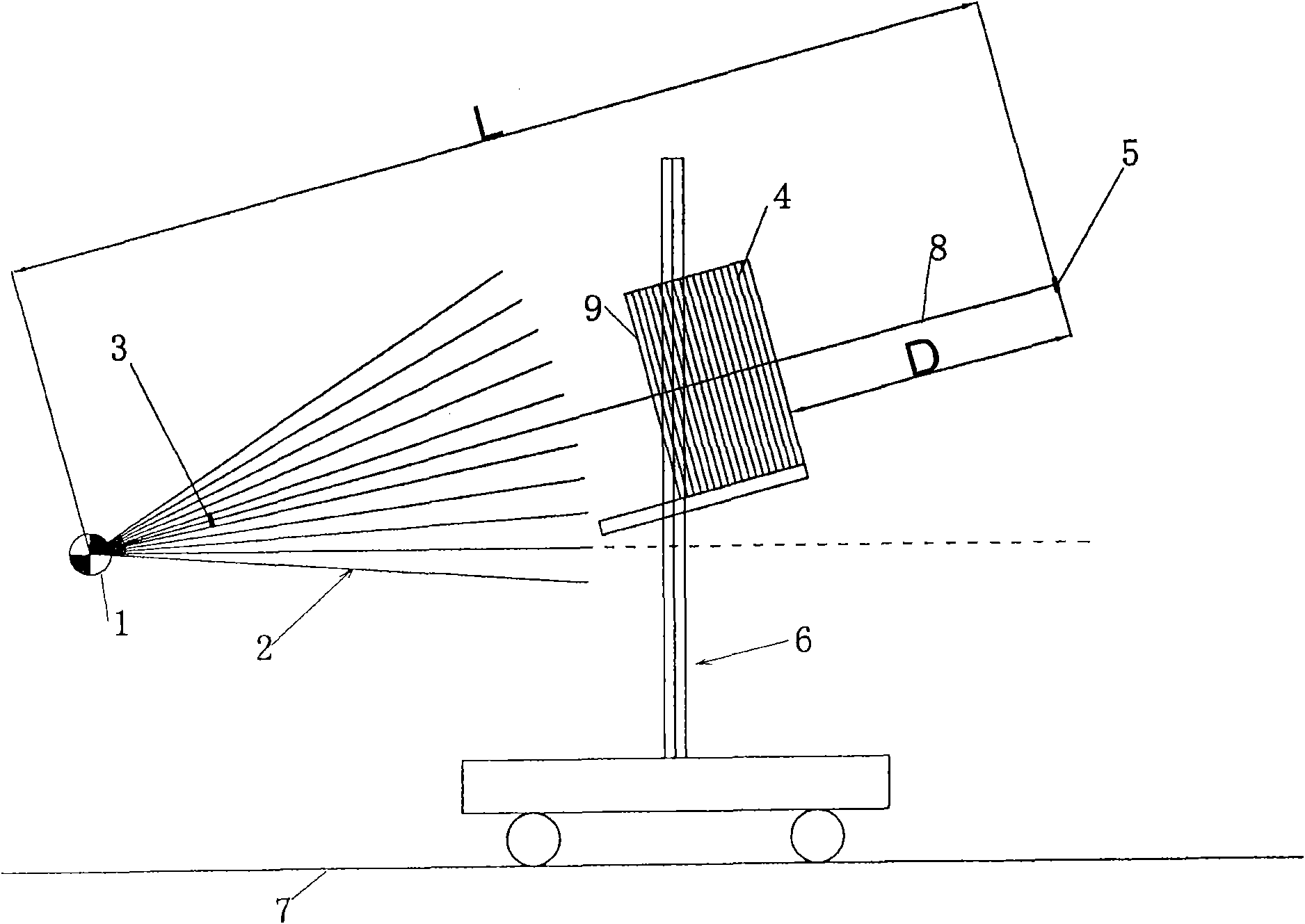
[0007] 3. Since the method is generally rough, there are no strict requirements on geometric layout and other parameters in the test. In fact, when the detector is close to the shielding block, a small distance change will have a greater impact on the measurement results.

Method used


Image

  • Method for measuring energy of accelerator
  • Method for measuring energy of accelerator
  • Method for measuring energy of accelerator

Examples


Embodiment Construction

[0018] The following examples are intended to illustrate the present invention, but not to limit the scope of the present invention.

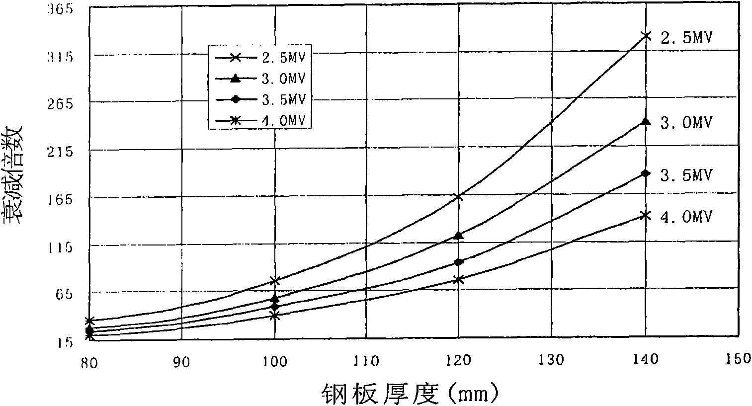
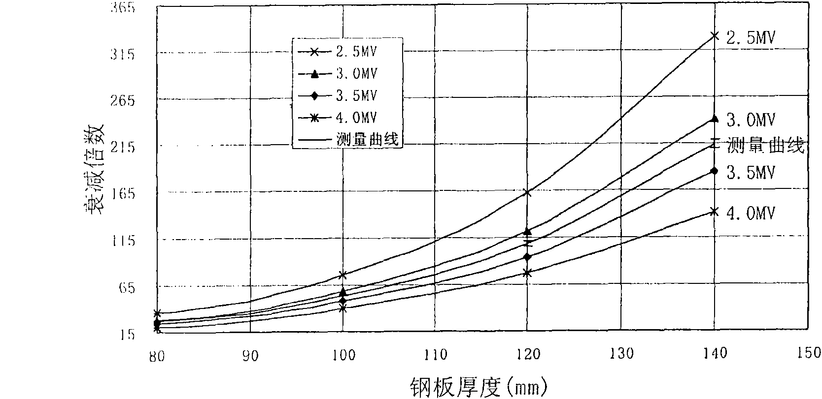
[0019] The method for measuring accelerator energy according to an embodiment of the present invention includes: a measuring step: measuring a measurement curve of the attenuation factor of the X-ray emitted by the accelerator as a function of the thickness of the shielding material, and a comparison step: comparing the measured measurement curve with a reference curve , thereby determining the energy of the X-rays emitted by the accelerator.

[0020] The measurement curve of the change of the attenuation factor of X-ray with the thickness of shielding material, namely the KD curve, is the change curve of the attenuation factor of X-ray after passing through the shielding material of different thickness. The shielding material here may include various inorganic and organic materials such as tungsten, steel, lead, aluminum, water, and crystal. ...


PUM


Abstract

The invention discloses a method for measuring the energy of an accelerator, comprising the following steps: a measuring step for measuring a measurement curve that an attenuation multiple of an X ray from an accelerator is changed along with the thickness of a shielding material; and a comparing step for comparing the measurement curve with a reference curve to determine the energy of the X ray from the accelerator. The method can accurately judge the actual energy of the X ray beam from the electronic accelerator. The method is not limited from the restriction condition of the accelerator, and has the characteristics of low cost, simple operation, vivid data, high precision and small error caused by artificial factor. The method is not only suitable for the quality control of the production, debugging and check of the accelerator in the nuclear technology but also capable of guiding the operator to debug the accelerator precisely.

Description

technical field [0001] The invention relates to a method for measuring accelerator energy, in particular for the determination of X-ray energy generated by accelerators in the field of nuclear technology applications. Background technique [0002] In the application field of nuclear technology, it is very important to determine the energy of the X-ray beam emitted by the accelerator. At present, in the energy test of industrial accelerators, the most commonly used measurement method is the half-value layer method of steel materials, namely: [0003] Select a fixed position in the beam direction of the accelerator, place a certain number of steel plates with the same thickness in the vertical beam direction, and place the detector near the steel plate. The signal of the detector after measuring the X-rays passing through different effective steel plate thicknesses is relatively unaffected. A series of ratios of detector signals for any steel plate are fitted into a curve, and...

Claims


Application Information

Patent Timeline
Patent Type & Authority Applications(China)
IPC IPC(8): G01T1/02
Inventor 邓艳丽朱国平苗齐田王兵曹艳锋明申金
Owner NUCTECH BEIJING CO LTD
Learn More