
Method for connecting electrolytic aluminum anode without pouring

A technology of electrolytic aluminum anode and connection method, applied in the field of pour-free connection of electrolytic aluminum anode, can solve the problems of increasing the voltage drop of the conductive device, increasing the energy consumption, high labor intensity, etc., so as to increase the conductive contact area and reduce the conductive The effect of voltage drop and labor intensity reduction

Inactive Publication Date: 2012-07-25
商丘市鑫科节能技术服务有限公司
View PDF0 Cites 2 Cited by
  • Summary
  • Abstract
  • Description
  • Claims
  • Application Information

AI Technical Summary

Problems solved by technology

The connection method adopted has high energy consumption, high cost per ton of aluminum, high labor intensity and poor working conditions.
During the use of the anode, the current is conducted to the anode carbon block through the poured ferrophosphorus. Since the contact between the ferrophosphorus and the anode carbon block is not good, the voltage drop of the entire conductive device is increased, and the energy consumption is increased.
At the same time, after the anode carbon block is used, when cleaning the steel claws, it is necessary to take off the phosphorous iron rings poured on the steel claws, which is labor-intensive and time-consuming, and pollutes the environment

Method used


Image

  • Method for connecting electrolytic aluminum anode without pouring
  • Method for connecting electrolytic aluminum anode without pouring
  • Method for connecting electrolytic aluminum anode without pouring

Examples


Embodiment Construction

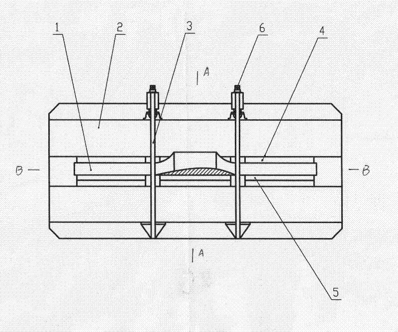
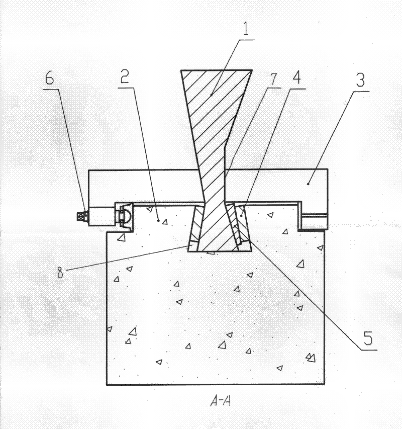
[0010] as attached figure 2 As shown, the cross section of the steel claw 1 is made into a wedge shape with a large bottom and a small top, and the wedge shape is asymmetrical. The angle on the left is 1.5°, and the angle on the right is 3°. The anode carbon block 2 is made into a boss shape in cross section. In the middle of the upper plane, a dovetail-shaped through groove 8 is opened longitudinally. The angle of the two side walls of the dovetail-shaped through-groove 8 is equal to the side with the smaller angle of the steel claw. The cross-section of the dovetail-shaped through-groove 8 is larger than that of the steel claw 1. After the steel claw 1 is put into the dovetail-shaped through groove 8, three copper plates 4 with the same thickness are correspondingly put into the gaps on both sides of the steel claw 1 (as attached figure 1 As shown), on the side of the steel claw 1 with a larger angle, a stainless steel wedge plate 5 with the same angle as the gap is filled ...


PUM


Abstract

The invention provides a method for connecting an electrolytic aluminum anode without pouring. In the method, a steel talon is manufactured into a wedge shape with a big end down cross section; the cross section of an anode carbon block is made into a boss shape, and a dovetail through slot is formed in the middle of the upper plane of the anode carbon block along the vertical direction; after the steel talon is put in the dovetail through slot, steel plates with the same number and same thickness are filled in gaps on two sides of the steel talon correspondingly, so that the two sides of thesteel talon and the copper plates are closely jointed, and the two steel plates and the anode carbon blocks on two sides are closely jointed. The pouring connecting method of melting ferro-phosphorusis changed into a wedge plate compacting connecting method, an intermediate frequency furnace for melting ferro-phosphorus and pressure-disengaging equipment for disengaging a phosphorus iron hoop bypressure are canceled, so that the equipment investment is reduced, the labor intensity is reduced, and the working environment is improved; the profile steel talon is put in the dovetail through slot of the carbon block and compacted by a wedge-shaped stainless steel plate without pouring, so the operation is easy and convenient; and the conventional mode of combining the anode steel talon and the anode carbon block is changed, a transitional connecting mode of combining copper and carbon is adopted, so that the conductive contact area is enlarged, and the anode conductive drop can be effectively reduced.

Description

technical field [0001] The invention relates to a method for connecting an anode carbon block and a steel claw in electrolytic aluminum production. Background technique [0002] In the production of electrolytic aluminum, the anode is used as one of the raw materials for production, and the consumption per ton of aluminum is very large. In order to meet the needs of production, the general electrolytic aluminum factories at home and abroad use molten phosphorus iron juice to pour the anode carbon block and steel claw together. The connection method adopted has high energy consumption, high cost per ton of aluminum, high labor intensity and poor working conditions. During the use of the anode, the current is conducted to the anode carbon block through the poured ferrophosphorus. Since the contact between the ferrophosphorus and the anode carbon block is not good, the voltage drop of the entire conductive device is increased, and the energy consumption is increased. Simultan...

Claims


Application Information

Patent Timeline
Patent Type & Authority Patents(China)
IPC IPC(8): C25C3/12
Inventor 张孝义郭海军李巨东赵请宇张进一安敬江杨昇谢新雨丁永恒欧建明
Owner 商丘市鑫科节能技术服务有限公司
Learn More