
Magnetoresistive sensor arrangement for current measurement

一种磁阻传感器、传感器的技术,应用在测量装置、测量磁变量、测量电变量等方向

Active Publication Date: 2011-06-15
ABB (SCHWEIZ) AG
View PDF5 Cites 27 Cited by
  • Summary
  • Abstract
  • Description
  • Claims
  • Application Information

AI Technical Summary

Problems solved by technology

Therefore, due to the hysteresis effect of these materials, there will still be an offset

Method used


Image

  • Magnetoresistive sensor arrangement for current measurement
  • Magnetoresistive sensor arrangement for current measurement
  • Magnetoresistive sensor arrangement for current measurement

Examples


Embodiment Construction

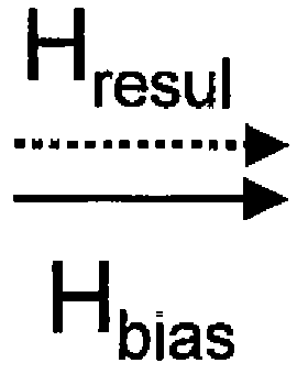
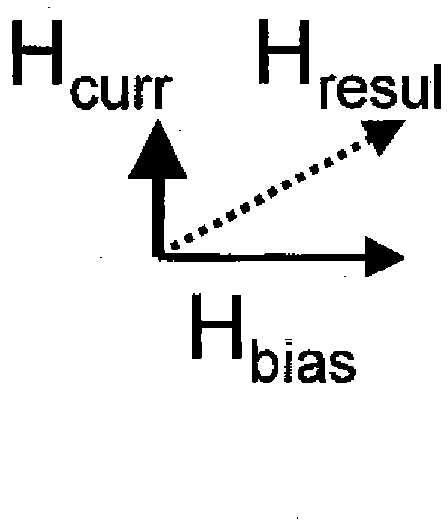
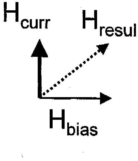
[0043] A magnetoresistive element used in a magnetoresistive sensor is an object that changes its electrical resistance as a function of the magnetization direction of the element for a small probe current passed through the element. The resistance depends approximately on the cosine square of the angle between the probe current and the magnetization of the material. If the current and magnetization point in the same direction, the resistance will be maximum. If the angle between the current flow and the magnetization is 90 degrees, the resistance will be minimal. The device was installed such that the probe current was inclined by 45 degrees relative to the main magnetic field to be measured, and the bias magnetic field was further inclined by another 45 degrees so that it was inclined by 90 degrees relative to the main magnetic field. In this case, the resistance of the magnetoresistive element is sensitive to the main magnetic field up to the point where the magnitude of t...


PUM

PropertyMeasurementUnit
diameteraaaaaaaaaa

Abstract

A sensor unit for the measurement of a current in a conductor (1) comprising at least one magnetoresistive sensor (5, 6) located at a radial distance from the outer surface of the conductor (1) is disclosed, wherein the conductor (1) has a circular cross-section, and wherein it comprises at least one auxiliary coil (7) for the generation of a bias magnetic field (Hbias) to the magnetoresistive sensor (5, 6) strong enough for inducing magnetic saturation in the magnetoresistive sensor (5, 6) continuously during the whole current measurement process. Further the use of such a sensor and a method for measuring the current in the conductor using such a sensor unit are disclosed.

Description

technical field [0001] The invention relates to a sensor unit for measuring a current in a conductor comprising at least one magnetoresistive sensor, to the use of such a sensor unit, and to a method of measuring a current using such a sensor unit. Background technique [0002] Measuring small current signals above or after high current peaks is a challenging experimental task. Three different types of measurement techniques are commonly used to solve this problem: [0003] 1) The first measuring principle is based on integrating an additional resistance (so-called shunt resistor) into the circuit so that the current to be measured (main current) flows through it. The current is then drawn directly from the voltage drop across this additional resistance. [0004] However, there are difficulties associated with this measurement technique. On the one hand, the resistor must be chosen so that it does not affect the circuit, so this resistor must be much smaller than all the ...

Claims


Application Information

Patent Timeline
Patent Type & Authority Applications(China)
IPC IPC(8): G01R15/20G01R33/09
CPCB82Y25/00G01R15/205G01R33/093
Inventor 鲁道夫·加蒂马库斯·阿普拉纳尔普
Owner ABB (SCHWEIZ) AG
Learn More