Over-current or short-circuit state detection circuit of insulated gate bipolar transistor (IGBT)

A short-circuit state and detection circuit technology, applied in the circuit field, can solve problems such as inability to detect DC current, large current signal noise, and different tube voltage drop characteristics, and achieve the effects of fast protection speed, small delay, and strong circuit versatility

Inactive Publication Date: 2014-04-02
黄金亮
View PDF5 Cites 1 Cited by
  • Summary
  • Abstract
  • Description
  • Claims
  • Application Information

AI Technical Summary

Problems solved by technology

The disadvantage is that the Hall sensor works in a high-radiation environment, and the output current signal is noisy, which may easily cause system malfunction
The disadvantage is that this method cannot detect DC current
Its disadvantage is that it takes up a lot of area on the circuit board, requires an op amp and a comparator, and costs a lot
The disadvantage is that different types of power tubes have different tube pressure drop characteristics, and are also affected by the operating temperature
Its disadvantages are: the three emitter pins of the lower bridge arm of the IGBT are grounded through the shunt, and the voltage signal generated by the shunt will disturb the gate drive signal of the IGBT; this kind of protection circuit can only cooperate with specific modules, and has poor versatility

Method used


Image

  • Over-current or short-circuit state detection circuit of insulated gate bipolar transistor (IGBT)
  • Over-current or short-circuit state detection circuit of insulated gate bipolar transistor (IGBT)
  • Over-current or short-circuit state detection circuit of insulated gate bipolar transistor (IGBT)

Examples


Embodiment Construction

[0028] The principles and features of the present invention are described below in conjunction with the accompanying drawings, and the examples given are only used to explain the present invention, and are not intended to limit the scope of the present invention.

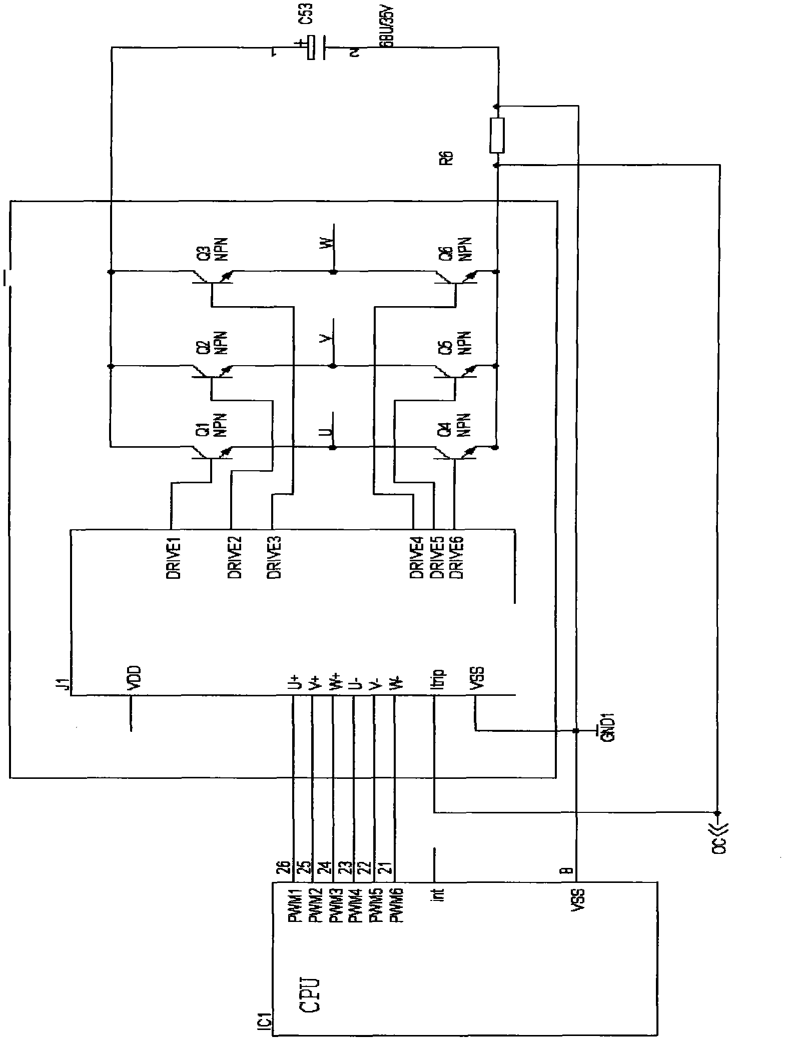
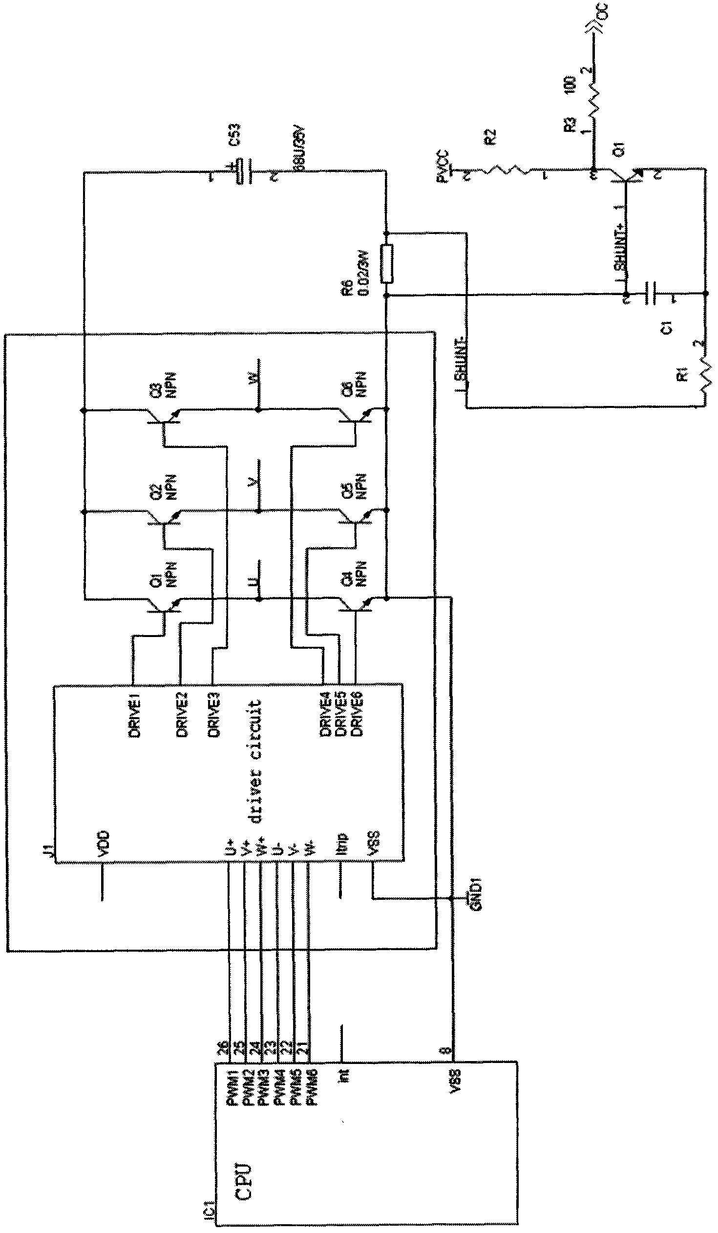
[0029] Such as figure 2 As shown, the IGBT overcurrent or short circuit state detection circuit of the present invention includes a shunt resistor R6 ( figure 2 not shown), capacitor C1, transistor Q1, resistor R1, resistor R2 and resistor R3; wherein, the shunt resistor R6 is a milliohm-level power resistor; one end of the shunt resistor R6 is electrically connected to the negative pole of the power voltage source at the node A, namely the I_SHUNT-node, the other end of the shunt resistor R6 is electrically connected to the emitter of the lower bridge arm of the power conversion circuit and the signal ground terminal of the IGBT drive circuit to node B, namely the I_SHUNT+ node; the base of the transistor Q1 and ...


PUM


Abstract

The invention relates to an over-current or short-circuit state detection circuit of an insulated gate bipolar transistor (IGBT), which comprises a branch circuit, a capacitor, a transistor, a resistor R1, a resistor R2 and a resistor R3, wherein one end of the branch circuit and a negative pole of a power voltage source are electrically connected at a node A, and the other end of the branch circuit, an emitter of a lower bridge arm of a power conversion circuit and a signal grounding terminal of an IGBT driving circuit are electrically connected at a node B; a switching control pole of the transistor and one end of the capacitor are electrically connected at the node B; one end of the resistor R1 is electrically connected at the node A; the other end of the capacitor and the other end of the resistor R1 are electrically connected with a second pole of the transistor; a third pole of the transistor is electrically connected with one end of the resistor R2 and one end of the resistor R3 respectively; the other end of the resistor R2 is connected with high-level chlorinated polyvinyl chloride (PVCC); and the other end of the resistor R3 outputs a guard signal OC. The detection circuit provided by the invention has the advantages of few used elements, low cost, small occupied area of a printed circuit board (PCB) and quick and reliable response, the reduced pressure of the branch circuit does not have disturbance to the IGBT driving circuit, and the power conversion can not influence the reliability and stability of operation.

Description

technical field [0001] The invention belongs to the field of circuits, and in particular relates to a circuit for protecting IGBT from overcurrent and short circuit. Background technique [0002] IGBT (Insulated Gate Bipolar Transistor, insulated gate bipolar transistor) is the core device of modern power conversion technology, and its overcurrent and short circuit protection play a very important role in the reliability of the entire conversion equipment. [0003] At present, there are several ways to protect the insulated gate bipolar transistors: [0004] 1) Use a Hall current sensor to detect the output current of the power conversion device, set up a current-limiting threshold, compare with a comparator, and output an over-current protection signal. The disadvantage is that the Hall sensor works in a high-radiation environment, and the output current signal is noisy, which may easily cause system malfunction. At the same time, the Hall device is very expensive, and th...

Claims


Application Information

Patent Timeline
Patent Type & Authority Patents(China)
IPC IPC(8): H02H7/20G01R31/02G01R19/165
Inventor 黄金亮
Owner 黄金亮
Why Eureka
Try Eureka