Vacuum circuit breaker with electromotive force compensation circuit

A technology of vacuum circuit breaker and compensation circuit, applied in the direction of high-voltage air circuit breaker, circuit, electric switch, etc., can solve the problems of unfavorable electric compensation force directly acting on vacuum interrupter, loosening, increasing the depth of circuit breaker, etc.

Active Publication Date: 2013-03-20
CHANGSHU SWITCHGEAR MFG CO LTD (FORMER CHANGSHU SWITCHGEAR PLANT)
View PDF6 Cites 0 Cited by
  • Summary
  • Abstract
  • Description
  • Claims
  • Application Information

AI Technical Summary

Problems solved by technology

[0006] Although the above two patent schemes achieve the effect of electrodynamic compensation in the same way but with the same results, since the electrical connection between the conductor, that is, the soft connection, and the moving conductive rod (also called the moving contact end) of the vacuum interrupter is through the top vertical screw It is reflected by tightening (tightening), and because the top vertical screw also serves as a mechanical connection for transmitting the mechanical power of the operating mechanism, therefore, after the circuit breaker is frequently operated, the mechanical connection part will be due to vertical (longitudinal) vibration. And there is looseness, which leads to unreliable electrical connection and easy to cause accidents.
In addition, it can also be seen from the above two electrodynamic compensation schemes that since the U-shaped loops of the soft connection are arranged on one side of the vacuum interrupter and are far away from the vacuum interrupter, the depth of the circuit breaker is increased and the circuit breaker is restricted. The miniaturization of the device volume is not conducive to the direct action of the electric compensation force on the vacuum interrupter

Method used


Image

  • Vacuum circuit breaker with electromotive force compensation circuit
  • Vacuum circuit breaker with electromotive force compensation circuit
  • Vacuum circuit breaker with electromotive force compensation circuit

Examples


Embodiment Construction

[0028] In order to enable the public to fully understand the technical essence and beneficial effects of the present invention, the applicant will describe in detail the specific implementation of the present invention below in conjunction with the accompanying drawings, but the applicant's description of the embodiments is not a limitation to the technical solution. Changes in the form of the inventive concept rather than in substance should be regarded as the protection scope of the present invention.

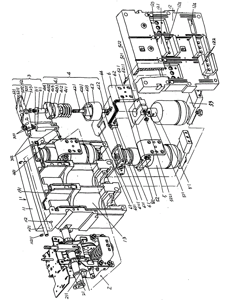
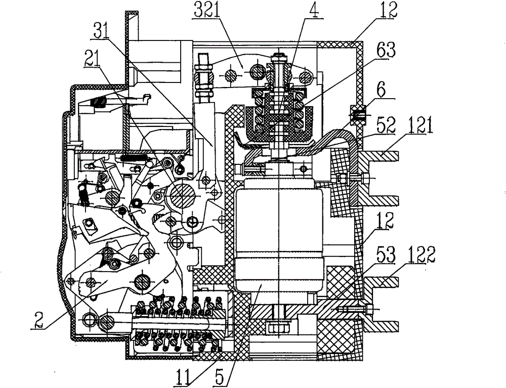
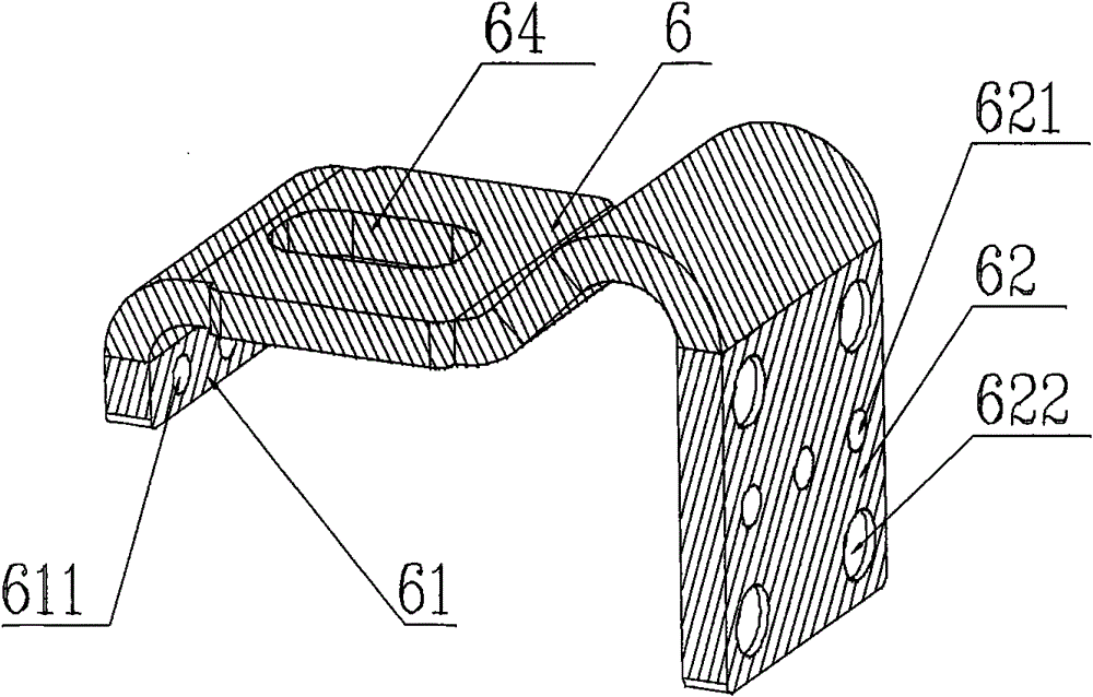
[0029] See figure 1, a vacuum circuit breaker with an electrodynamic compensation circuit of the present invention includes a housing 1, an operating mechanism 2, a set of vacuum interrupters 5, an upper busbar 121 and a lower busbar 122, and the housing 1 includes a The base 11, a base plate 12 and a group of vacuum interrupter cavities 13 whose number is equal to the number of the vacuum interrupter 5, the base plate 12 is matched with the base 11, that is, both are covered...


PUM


Abstract

The invention discloses a vacuum circuit breaker with an electromotive force compensation circuit, which belongs to the technical field of low voltage apparatuses. The vacuum circuit breaker comprises a shell, an operation mechanism, a group of vacuum arc extinguish chambers, a group of upper busbars and a group of lower busbars, wherein the operation mechanism is arranged on the shell; the group of vacuum arc extinguish chambers is arranged on the shell and driven by the operation mechanism; the number of the upper busbars is equal to that of the vacuum arc extinguish chambers; the group of upper busbars are electrically connected with the upper ends of the vacuum arc extinguish chambers; the number of the lower busbars is equal to that of the vacuum arc extinguish chambers; and the group of lower busbars are electrically connected with the lower ends of the vacuum arc extinguish chambers. The vacuum circuit breaker is characterized in that: the upper ends of the vacuum arc extinguish chambers are fixed with an upper conductive block respectively; a flexible connector is arranged above each upper conductive block; one end of the flexible connector is extended downwards, and is fixedly connected with one side, facing the operation mechanism, of the upper conductive block so as to form a [-shaped conductive path by the flexible connector and the upper conductive block; and the other end of the flexible connector is extended towards the upper busbar, and is fixedly connected with the upper busbar. The vacuum circuit breaker has the advantages of meeting the requirements of miniaturization on the volume of the circuit breaker and obtaining relatively stronger electromotive compensation forces directly acting on the vacuum arc extinguish chambers.

Description

technical field [0001] The invention belongs to the technical field of low-voltage electrical appliances, and in particular relates to a vacuum circuit breaker with an electric power compensation circuit. Background technique [0002] As is well known in the industry, in low-voltage power distribution systems, circuit breakers have the functions of distributing power, protecting power circuits and electrical equipment, and avoiding hazards caused by overload, negative voltage, short circuit and / or ground fault. At present, it has gradually become a reality to reduce power loss and expand the power transmission radius by increasing the voltage of the power transmission and distribution system and the working voltage of the terminal appliances, so that the application of vacuum circuit breakers in this power transmission and distribution system has more advantages. This is because: firstly, since the vacuum universal circuit breaker is insensitive to the voltage when breaking ...

Claims


Application Information

Patent Timeline
Patent Type & Authority Patents(China)
IPC IPC(8): H01H33/66H01H33/664
Inventor 周敏琛钱锦丰俞晓峰管瑞良
Owner CHANGSHU SWITCHGEAR MFG CO LTD (FORMER CHANGSHU SWITCHGEAR PLANT)
Why Eureka
Try Eureka