
Wavefront detection and reconstruction method based on differential sensor

A wavefront detection and sensor technology, applied in the direction of instruments, measuring devices, scientific instruments, etc., can solve problems such as no wavefront reconstruction method given

Inactive Publication Date: 2011-06-15
NANJING INST OF ASTRONOMICAL OPTICS & TECH NAT ASTRONOMICAL OBSE
View PDF6 Cites 6 Cited by
  • Summary
  • Abstract
  • Description
  • Claims
  • Application Information

AI Technical Summary

Problems solved by technology

U.S. Patent US2006 / 0175528 proposed the concept of differential sensor based on diffractive optical elements, and proved that the output information of the differential sensor has a certain correspondence with the size and position of the measured distortion wavefront information, but did not give further wavefront reconstruction method

Method used


Image

  • Wavefront detection and reconstruction method based on differential sensor
  • Wavefront detection and reconstruction method based on differential sensor
  • Wavefront detection and reconstruction method based on differential sensor

Examples


Embodiment Construction

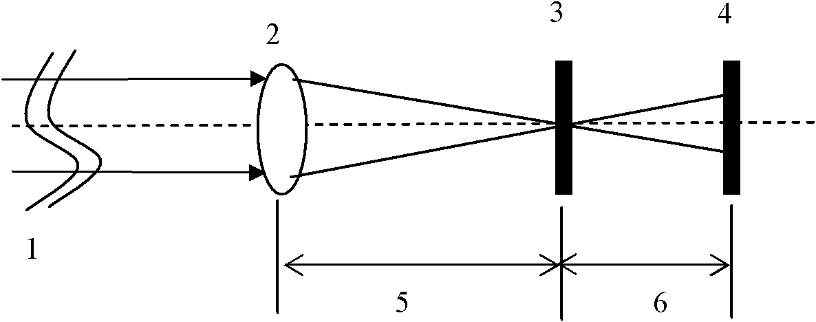
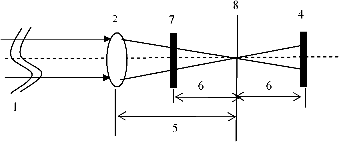
[0048] like image 3 As shown, the wavefront to be measured is imaged on the CCD through the combination of lens L1 and lens grating, and a CCD camera is placed near the focal plane to record the +1 order and -1 order diffraction images of the distorted wavefront, the +1 order and -1 order in the figure The 1st order image is an example of practical application. Then the two-dimensional light intensity distribution information of the two diffraction images is simultaneously collected into the computer by the image acquisition card. Then, the signal difference Dr is decomposed and processed by the phase reconstruction algorithm, and finally the restored wavefront to be measured is obtained.

[0049] The specific implementation process of the wave front of the present invention is as follows:

[0050] (1) Find a set of suitable spatial decomposition patterns. Due to the orthogonality of the Zernike mode and its versatility in describing optical aberrations, the Zernike mode c...


PUM


Abstract

The invention relates to a wavefront detection and reconstruction method based on a differential sensor. The method is characterized by comprising the following steps of: imaging a wavefront to be tested on a CCD (Charge Coupled Device) through combining a lens L1 and a lens grid; arranging a CCD camera near a focal plane to record diffraction images of +1 order and -1 order of distortion wavefront; then, simultaneously collecting the two-dimensional light intensity distribution information of the two diffraction images in the two former steps into a computer by an image acquisition card; carrying out mode decomposition and processing to a signal difference Dr by the computer through using a phase reconstruction algorithm; and finally acquiring the restored wavefront to be tested. Without calibration beforehand, the realizing process is simple, the practicability is higher, the added errors are reduced, no sub-caliber light splitting is carried out, and the light energy utilization is improved. The method with less calculation quantity and high calculation speed can be applied to the application fields with higher real-time property requirement, such as adaptive optics, and the like and has stronger anti-noise capability.

Description

technical field [0001] The invention belongs to the technical field of optical information measurement, and relates to a method for measuring the wavefront of an incident light beam, in particular to a wavefront detection and reconstruction method based on a differential sensor (a null sensor). The invention is suitable for application fields such as adaptive optics system and optical detection. Background technique [0002] In applications such as optical inspection and adaptive optics, it is necessary to measure the wavefront of a beam of light. At present, many methods of wavefront measurement have been developed, which can be roughly divided into two categories: (1) Measure the slope of the wavefront, and then restore the phase distribution of the wavefront through certain wavefront detection and reconstruction algorithms. These include Hartmann wavefront sensor and shear interferometer, etc.; (2) measure the light intensity distribution on different planes in the optic...

Claims


Application Information

Patent Timeline
IPC IPC(8): G01J9/00
Inventor 张思炯杨慧珍
Owner NANJING INST OF ASTRONOMICAL OPTICS & TECH NAT ASTRONOMICAL OBSE
Learn More