
Lead screw thread pitch detector

A detector and lead screw technology, applied in the field of lead screw pitch detectors, can solve the problems of inaccuracy, high cost, influence on workpiece accuracy, etc., and achieve the effects of simple overall structure, low equipment cost, and accurate measurement

Inactive Publication Date: 2011-06-15
大连机床(数控)股份有限公司
View PDF5 Cites 15 Cited by
  • Summary
  • Abstract
  • Description
  • Claims
  • Application Information

AI Technical Summary

Problems solved by technology

[0002] Screws are commonly used components in machining equipment or other equipment. Most of them are used in transmission mechanisms. After the screw is processed, it is necessary to detect the pitch of the screw. At present, there are two main ways to detect the pitch. One is The vernier caliper is used for measurement, and the reading is distinguished by the human eye on the scale, which is inaccurate and has a large error. In addition to the error of the vernier caliper itself, the final measured value is not accurate and affects the accuracy of the workpiece; another way is to use it under dynamic conditions. Laser equipment is used for measurement, resulting in complex structure of detection equipment, troublesome operation and high cost

Method used


Image

  • Lead screw thread pitch detector
  • Lead screw thread pitch detector
  • Lead screw thread pitch detector

Examples


Embodiment Construction

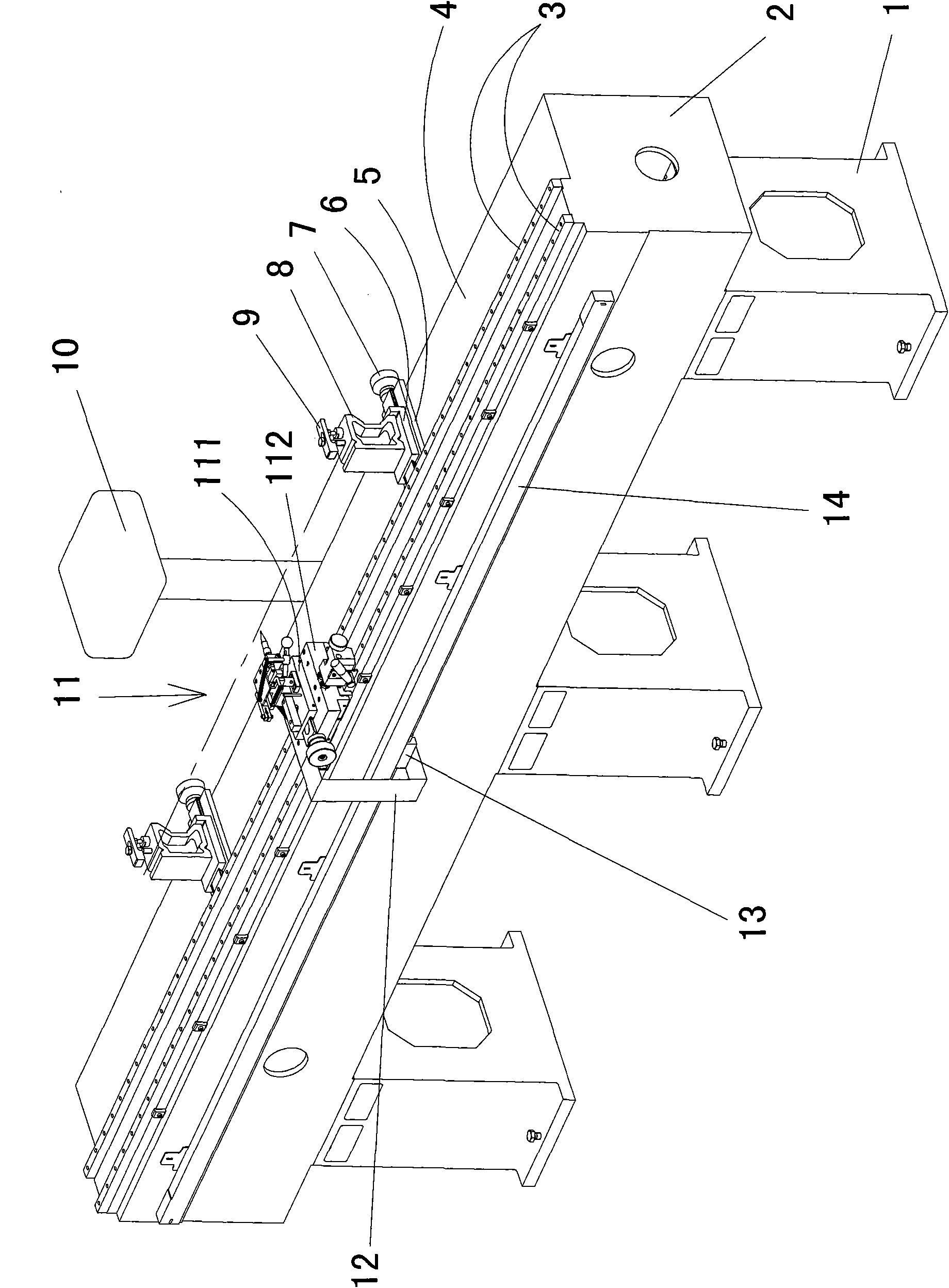
[0017] like figure 1 As shown: 1 is a bracket, and there are three brackets 1, and a base 2 is fixedly connected with a bolt above the bracket 1, and the base 2 is in the shape of a strip.

[0018] One side above the base 2 is longitudinally connected with two parallel guide rails 3 by screws, and the guide rails 3 are linear guide rails. A support surface 4 is processed on the other side of the base 2, and the longitudinal direction of the guide rail 3 is parallel to the support surface 4 and is also in a horizontal state.

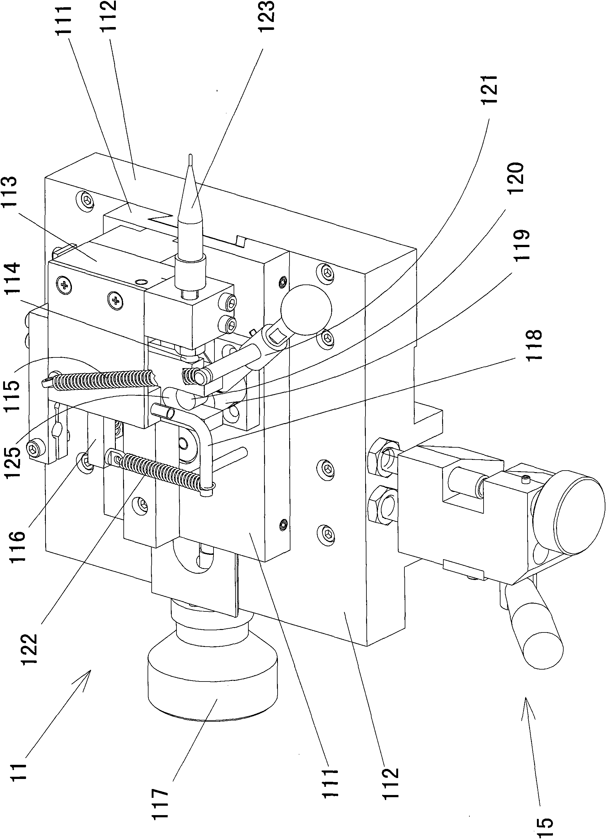
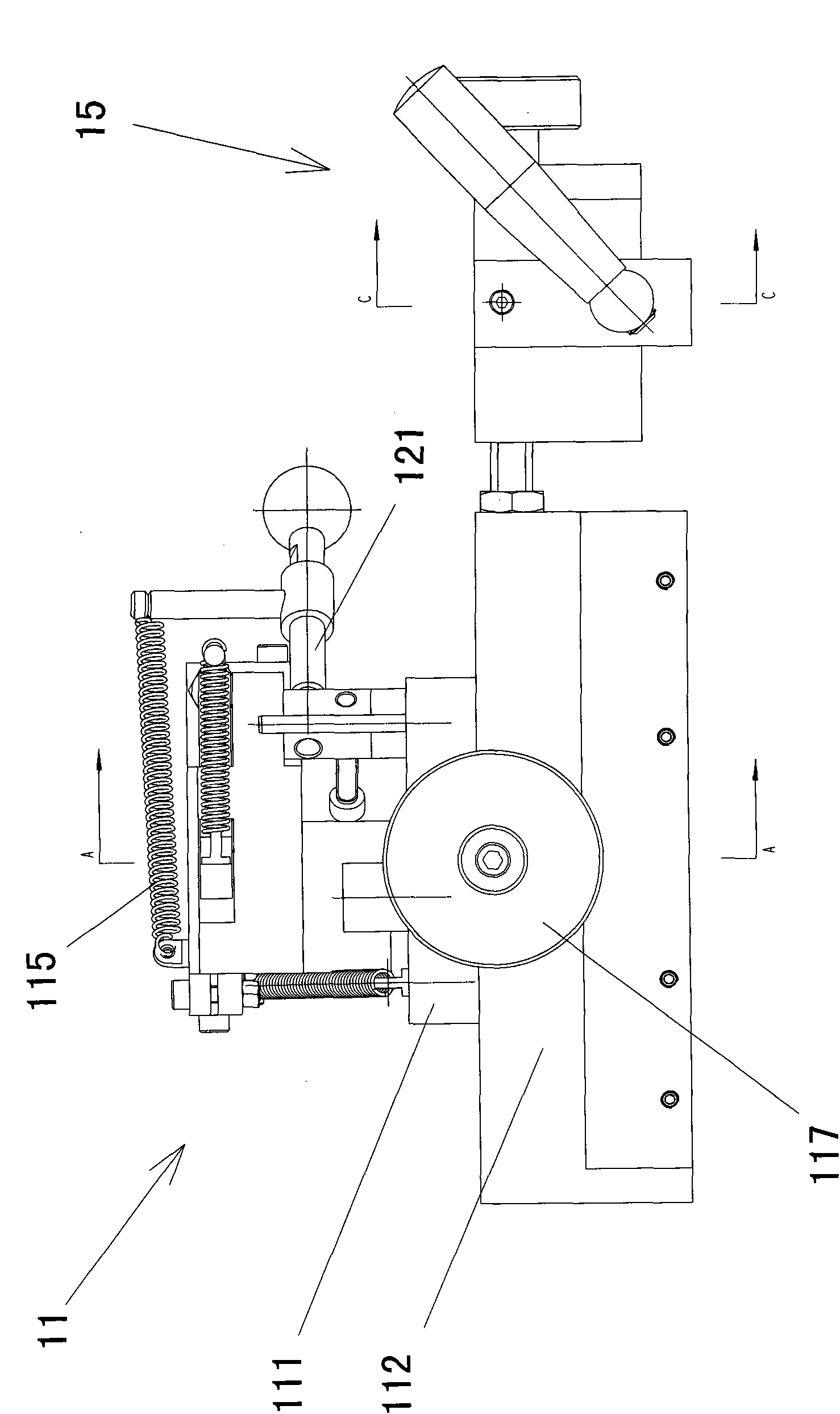
[0019] A measuring mechanism 11 is mounted on the linear guide rail 3 .

[0020] A grating scale 14 parallel to the guide rail 3 is fixedly connected to the side of the base 2 by screws, and the reading head 13 matched with the grating scale is connected to the sliding platform 112 in the measuring mechanism 11 through the connecting plate 12 . The other side of the base 2 is fixedly connected with a vertical pole, and a digital display meter 10 is scre...


PUM


Abstract

The invention discloses a lead screw thread pitch detector comprising a bracket, wherein a strip-shaped substrate is fixedly connected to the upper part of the bracket; one side of the upper part of the substrate is longitudinally provided with a guide rail, and the other side of the upper part of the substrate is provided with a supporting surface; the longitudinal direction of the guide rail isparallel to the supporting surface; the guide rail is provided with a measuring mechanism; the side edge of the substrate is provided with a grating scale parallel to the guide rail; a reading head matched with the grating scale is connected with the measuring mechanism by a junction plate; the other side of the substrate is provided with a digital display meter; the digital display meter is matched with the reading head and connected with the reading head via a data line; the supporting surface is provided with a workpiece support plate provided with a movable sliding table; and a workpiece support is arranged on the upper part of the movable sliding table. Compared with the prior art, the detector has the advantages of simple integral structure and low equipment cost, is easy to operateand control, is accurate to measure and is more suitable for longer lead screws.

Description

technical field [0001] The invention relates to a workpiece detector, in particular to a lead screw pitch detector, which is used to detect the lead screw pitch under static conditions. Background technique [0002] Screws are commonly used components in machining equipment or other equipment. Most of them are used in transmission mechanisms. After the screw is processed, it is necessary to detect the pitch of the screw. At present, there are two main ways to detect the pitch. One is The vernier caliper is used for measurement, and the reading is distinguished by the human eye on the scale, which is inaccurate and has a large error. In addition to the error of the vernier caliper itself, the final measured value is not accurate and affects the accuracy of the workpiece; another way is to use it under dynamic conditions. Laser equipment is used for measurement, which leads to complex structure of detection equipment, troublesome operation and high cost. Contents of the inve...

Claims


Application Information

Patent Timeline
IPC IPC(8): G01B5/14G01B11/14
Inventor 田杰石磊刘洋王俊杰
Owner 大连机床(数控)股份有限公司
Learn More