
Method and device for disassembling electrical-electronic apparatuses

A technology for electronic equipment and power, applied in the field of decomposing power electronic equipment and devices, can solve problems such as damage, pollution, and fragile backlight fluorescent tubes, and achieve the effect of less separation and less damage

Inactive Publication Date: 2011-06-15
GH ELECTROTERMIA
View PDF0 Cites 4 Cited by
  • Summary
  • Abstract
  • Description
  • Claims
  • Application Information

AI Technical Summary

Problems solved by technology

Unlike the plasma display units described above, the layers that make up the display unit are easily separated, but the backlight fluorescent tubes are very fragile and can be damaged when handled to remove them from the unit
[0006] Damage to fluorescent tubes is dangerous for operators and contamination is caused by diffusion of contaminating agents such as phosphorus and mercury present in them

Method used


Image

  • Method and device for disassembling electrical-electronic apparatuses
  • Method and device for disassembling electrical-electronic apparatuses
  • Method and device for disassembling electrical-electronic apparatuses

Examples


Embodiment Construction

[0030] The present invention will now be described based on the aforementioned drawings.

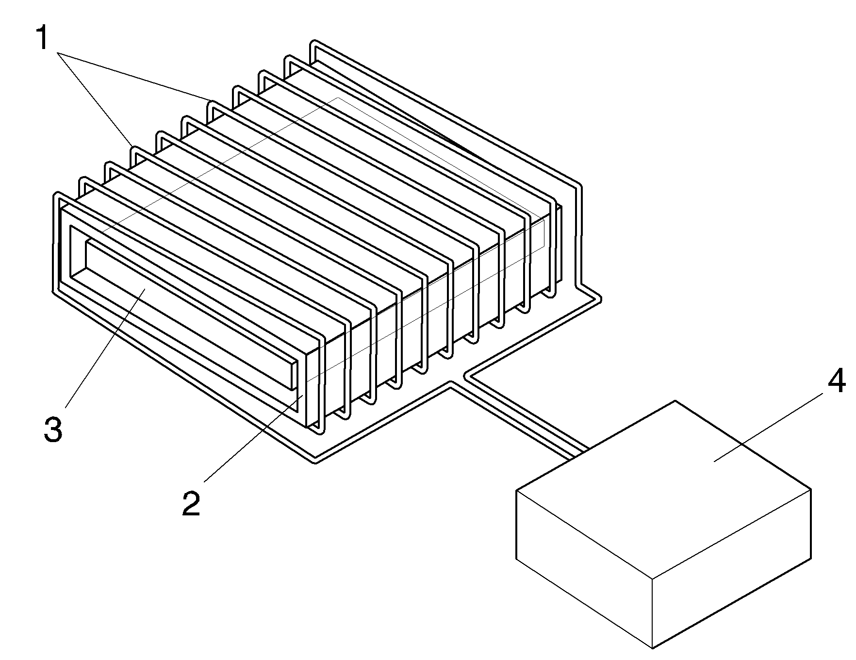
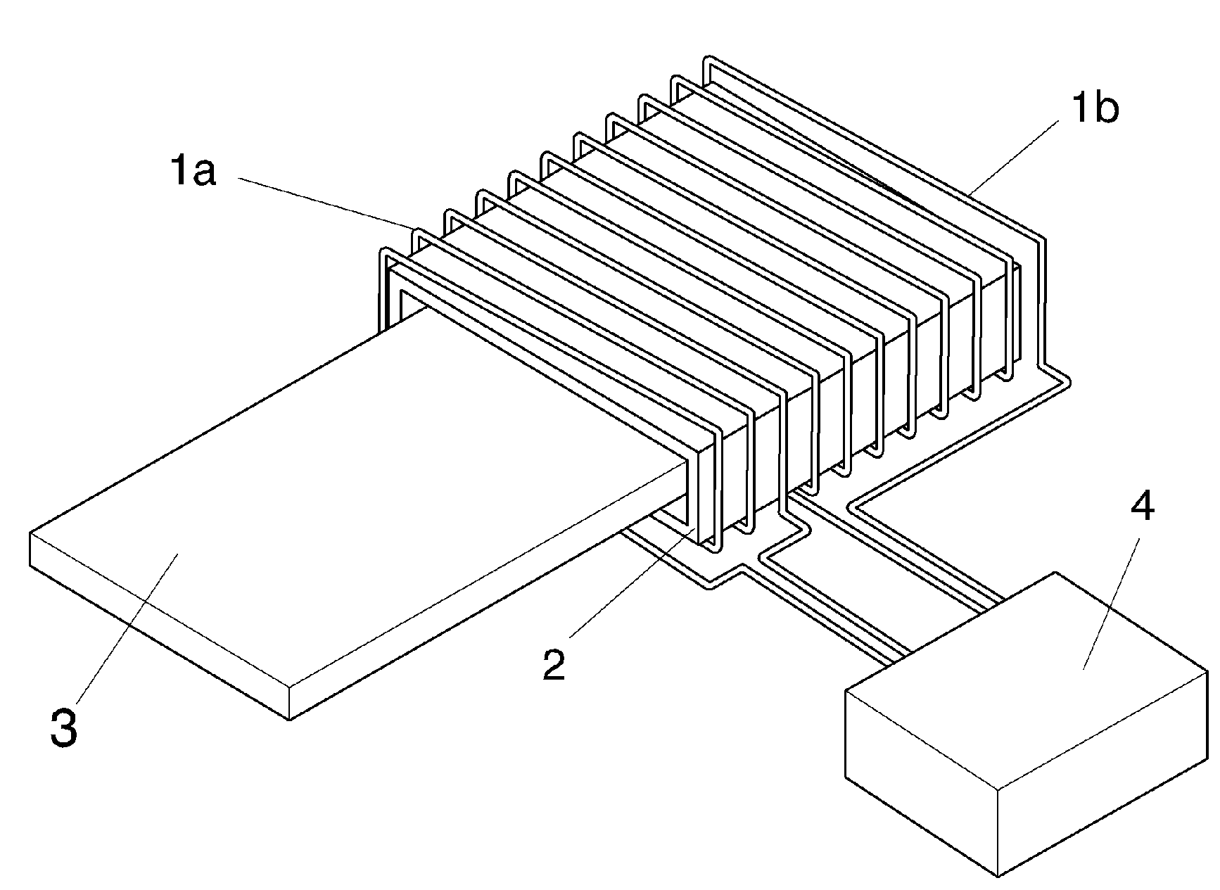
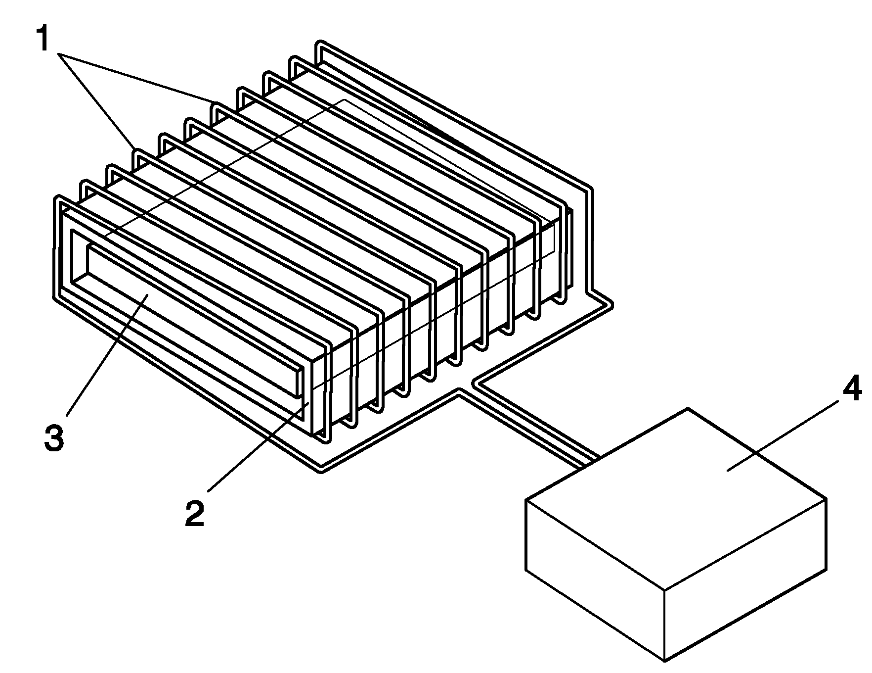
[0031] The device of the invention comprises an induction coil 1 comprising a set of turns wound around a tubular body 2 inside which the device 3 to be dismantled is housed. The induction coil 1 is connected to an alternating current generator 4 .

[0032] In a preferred embodiment example, the device 3 comprises a plasma display device such that the tubular support 2 has a rectangular cross-sectional configuration complementary to the rectangular cross-section presented by the plasma display device.

[0033] When the alternating current generator 4 is energized, this configuration allows current to circulate through the coil 1 to induce a current in the metal plates of the plasma display device, which heats the display device by means of convection, radiation and conduction and expand to the surrounding space. As a result, the connection points of the different sheets making up the p...


PUM


Abstract

The invention relates to a method and device for disassembling electrical-electronic apparatuses. The device comprises an induction coil (1, 1a, 1b) located around a tubular support (2) wherein the device (3) to be disassembled is housed, and it includes an alternating current generator (4) that feeds the coil in order to melt the thermoplastic material joints of the device by induction heating a metallic element of said device, which allows performing the manual disassembly of the elements constituting the device. An application is the recycling of screen displays. The invention is also related to a method that incorporates some steps according to that described for the device.

Description

technical field [0001] As indicated in the title of this description, the invention relates to methods and devices allowing to perform disassembly and disassembly of electrical and / or electronic equipment. The invention is applicable to any device in which the constituent elements are assembled at least from thermoplastic joints, wherein at least one of said elements is a metal element, and is used to generate heating of the metal elements, whereby the thermoplastic joints are heated and Melting, which allows performing manual decomposition of the elements that make up the device. [0002] In general, the present invention can be applied to any electric / electronic device satisfying the above-mentioned conditions, and more specifically, can be applied to realize a display device based on a liquid crystal display (LCD), a TFT (thin film transistor), or a plasma display recycling of TV or data display equipment. Background technique [0003] In the prior art, plasma or LCD di...

Claims


Application Information

Patent Timeline
Patent Type & Authority Applications(China)
IPC IPC(8): B09B3/00
CPCB29K2705/00B29K2709/08B29B17/02B29L2031/3475B29L2031/3061B29C2035/0811Y02W30/62
Inventor P.莫拉塔拉马蒂内斯M.梅兹基达吉斯伯特J.R.罗塞洛马根J.霍尔丹马蒂内斯C.卡塞斯桑奇斯E.德德加西亚-桑塔马里亚
Owner GH ELECTROTERMIA
Learn More