Radio-frequency identification reader antenna

A reader and antenna technology, used in antenna supports/installation devices, instruments, loop antennas with ferromagnetic material cores, etc. problem, to achieve the effect of high reading success rate, reducing common mode interference, and long reading distance

Inactive Publication Date: 2011-06-08
杭州琅木达电子系统工程有限公司
View PDF4 Cites 0 Cited by
  • Summary
  • Abstract
  • Description
  • Claims
  • Application Information

AI Technical Summary

Problems solved by technology

[0009] 6. Compared with RFID products in other frequency bands, the data transmission rate of this frequency band is relatively slow
[0010] 7. The price of electronic tags is relatively expensive compared to other frequency bands
[0012] The antennas used in traditional low-frequency passive radio frequency readers generally use hollow copper wire coils, and data transmission and reception are completed in the same antenna coil. strong, which leads to a decrease in the success rate of reading and affects the user's use

Method used


Image

  • Radio-frequency identification reader antenna
  • Radio-frequency identification reader antenna
  • Radio-frequency identification reader antenna

Examples


Embodiment Construction

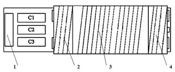
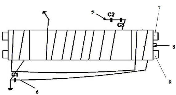
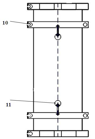
[0024] refer to figure 1 , figure 2 , image 3 The RFID reader antenna mainly includes the following parts: antenna skeleton, antenna circuit board 1, main coil 3, first sub-coil 2, second sub-coil 4, first ferrite core 7, second ferrite Core 9. The antenna circuit board 1 integrates various parts and connects with external circuits through its interfaces to form a whole. The main coil 3 of the antenna is wound at the center of the antenna skeleton tightly and uniformly, the first secondary coil 2 and the second secondary coil 4 are wound symmetrically at both ends of the antenna skeleton, the first ferrite core 7, the second The ferrite core 9 and the ferrite screw 8 are placed in the fixing hole 11 of the antenna frame to form the antenna body; then the antenna body is welded to the antenna circuit board 1 to form an LC resonance circuit with the capacitor on the antenna circuit board 1 .

[0025] ①The main coil 3 of the antenna is made of multi-strand yarn covered wir...


PUM


Abstract

The invention relates to a radio-frequency identification reader antenna which mainly comprises an antenna frame, an antenna circuit board 1, a main coil 3, a first auxiliary coil 2, a second auxiliary coil 4, a first ferrite core 7 and a second ferrite core 9. The technology ensures that the low-frequency antenna is characterized by omni-directional property, long reading distance, high sensitivity, high reading success rate and the like and has wide application range.

Description

technical field [0001] The present invention relates to an antenna, in particular to an antenna of a radio frequency reader. Background technique [0002] Radio Frequency Identification (RFID) technology is an automatic identification technology derived from the Allied aircraft identification technology during World War II. It realizes non-contact automatic identification through the principle of electromagnetic coupling or electromagnetic emission. The basic system of RFID includes two parts: electronic tag and reader, and its data communication is realized by electromagnetic coupling or electromagnetic emission between the antenna on the electronic tag and the antenna of the reader. The basic information code of the tracked item is stored in the electronic tag. When the electronic tag is within the range of the reader, its internal information will be quickly read by the reader, and the data will be transmitted (wireless or wired) Analyze and identify the computer applica...

Claims


Application Information

Patent Timeline
Patent Type & Authority Applications(China)
IPC IPC(8): H01Q1/14H01Q7/06G06K7/00
Inventor 廖铄
Owner 杭州琅木达电子系统工程有限公司
Why Eureka
Try Eureka