
Radio frequency identification RFID anti-metal microstrip tag antenna

A tag antenna, radio frequency identification technology, applied in the direction of antenna, antenna parts, antenna grounding device, etc., can solve the problems of destroying the antenna, low profile characteristics, increasing the size of the antenna, etc., to achieve long read and write distance, good impedance matching characteristics, high gain effect

Active Publication Date: 2021-02-23
10TH RES INST OF CETC
View PDF9 Cites 5 Cited by
  • Summary
  • Abstract
  • Description
  • Claims
  • Application Information

AI Technical Summary

Problems solved by technology

The bandwidth of the antenna can be effectively improved by adjusting the height of the dielectric layer. When the height of the dielectric layer increases, the bandwidth of the antenna will be widened and the efficiency of the antenna will be improved. However, increasing the height of the antenna will increase the volume of the antenna and destroy the Low profile characteristics of the antenna

Method used


Image

  • Radio frequency identification RFID anti-metal microstrip tag antenna
  • Radio frequency identification RFID anti-metal microstrip tag antenna
  • Radio frequency identification RFID anti-metal microstrip tag antenna

Examples


Embodiment Construction

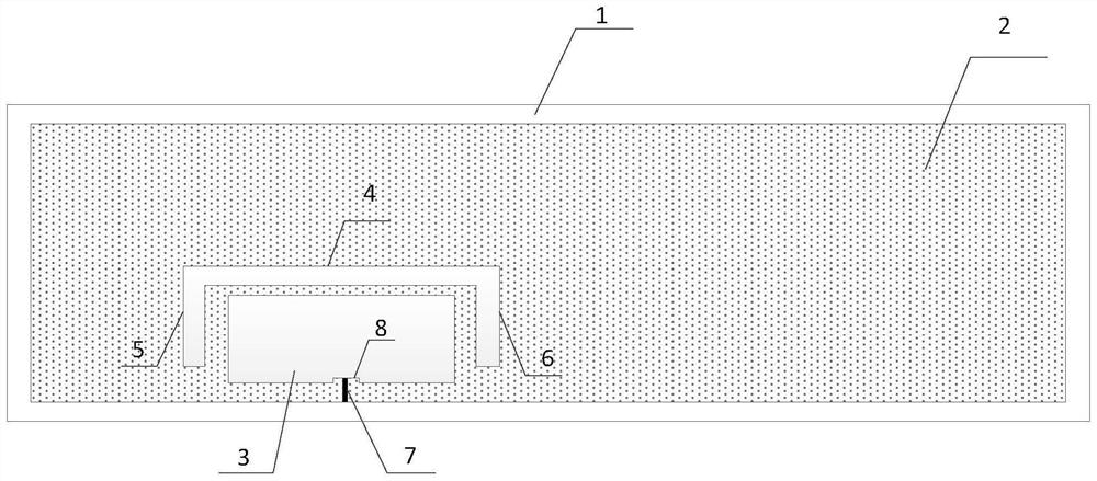
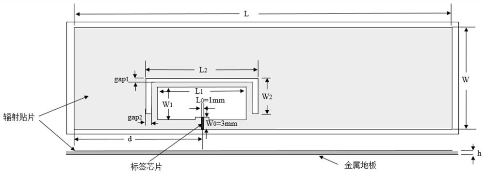
[0017] refer to figure 1. In the preferred embodiment described below, a radio frequency identification RFID anti-metal microstrip tag antenna includes: a radiation patch (2) arranged on the front side of the dielectric substrate (1) and a metal floor arranged on the back side of the dielectric substrate (1) , the radiation patch (2) forms a resonant cavity with the dielectric substrate (1) and the ground plane of the metal floor, which is characterized in that: the radiation patch (2) is provided with a rectangular groove (3) with the opening facing downwards, covering the rectangular The U-shaped groove of the groove (3) and the strip-shaped installation seam fixed with the RFID tag chip (7) electrically connected to the radiation patch (2); the first strip-shaped slit (4) is formed on the top of the U-shaped groove, left , the right side is shaped on the second strip-shaped slit (5) and the third strip-shaped slit (6); the bottom of the rectangular groove (3) is shaped on ...


PUM


Abstract

A radio frequency identification RFID anti-metal microstrip tag antenna disclosed by the invention is high in gain, low in cost and long in reading distance. According to the technical scheme, a radiation patch, a dielectric substrate and a metal floor form a resonant cavity, and the radiation patch covers a rectangular groove and is fixedly provided with a strip-shaped mounting seam of an RFID tag chip electrically connected with the radiation patch; a first strip-shaped gap is formed above a U-shaped groove, and a second strip-shaped gap and a third strip-shaped gap are formed in the left side and the right side of the U-shaped groove; and a protrusion is arranged at the bottom of the rectangular groove, one end of the strip-shaped mounting seam penetrates through the protrusion and is connected with the rectangular groove, the other end of the strip-shaped mounting seam penetrates through the bottom of the radiation patch, an edge field formed by gaps at the two ends of the U-shapedgroove generates radiation, and the metal floor, the radiation patch, a feeder line and a grounding line form an RFID anti-metal microstrip tag antenna. Based on the structure of the antenna and a slotting design, the performance of the tag is ensured under the condition that the thickness of the tag is reduced.

Description

technical field [0001] The invention relates to an ultra-high frequency radio frequency identification tag antenna applicable to a metal environment, in particular to a radio frequency identification RFID (Radio Frequency Identification, radio frequency identification) anti-metal microstrip tag antenna. Background technique [0002] Radio frequency identification RFID system has been widely used in public transportation, personnel identification, vehicle management, automatic toll collection, access control management and other fields. Radio frequency identification is RFID (Radio Frequency Identification) technology, also known as electronic tags and radio frequency identification. communication technology. RFID technology is a non-contact two-way communication using radio frequency, and it is also a short-range communication technology. It collects and identifies the relevant information of the target through radio frequency signals, and is widely used for its advantages...

Claims


Application Information

Patent Timeline
Patent Type & Authority Applications(China)
IPC IPC(8): H01Q1/22H01Q1/36H01Q1/38H01Q1/48
CPCH01Q1/2225H01Q1/36H01Q1/48H01Q1/38
Inventor 邓欣袁红刚娄宁何华武闫善勇
Owner 10TH RES INST OF CETC
Learn More