Wind wheel cable-stayed structure of wind driven generator with vertical shaft

A wind turbine, vertical axis technology, applied to wind turbines, wind turbines at right angles to the wind direction, motors, etc., can solve the problems of reduced generator service life, unstable operation of wind rotors, and reduced efficiency, and achieve reduced design The effect of manufacturing cost, increased running stability, and increased service life

Active Publication Date: 2011-06-08
NAT WIND ENERGY
View PDF11 Cites 6 Cited by
  • Summary
  • Abstract
  • Description
  • Claims
  • Application Information

AI Technical Summary

Problems solved by technology

These changes will lead to changes in the aerodynamic shape and characteristics of the wind rotor, reducing the wind power utilization coefficient of the wind rotor
The solution proposed by those skilled in the art for the above-mentioned problems is usually to make the support rod very strong, but the increase in the weight of the support rod results in a decrease in its efficiency, an increase in manufacturing cost, or even an unacceptable increase that cannot achieve the purpose of support. degree, and when the radius of the wind rotor is large, there will still be a large deflection even if the strength of the support rod is strengthened
[0004] (2) The fixed end of the support rod on the side of the tower, that is, the port of the generator rotor connection end, is subject to a large bending moment, which will easily cause damage to the generator and reduce the service life of the generator
[0005] (3) When the blade rotates to a different position relative to the direction of the incoming wind, the force is different. These forces of different sizes are amplified by the cantilever of the support rod, resulting in different speeds between the blades, resulting in vibration. These It will cause problems such as unstable operation of the wind wheel and vibration
[0006] (4) Due to the unreasonable form of force, the gravity transmission of the wind wheel is transmitted to the tower column through the support rod and the outer rotor of the generator, which not only increases the frictional resistance, reduces the power generation efficiency of the fan, but also leads to large fatigue stress of related components , the life guarantee design is difficult and the cost is high

Method used


Image

  • Wind wheel cable-stayed structure of wind driven generator with vertical shaft
  • Wind wheel cable-stayed structure of wind driven generator with vertical shaft
  • Wind wheel cable-stayed structure of wind driven generator with vertical shaft

Examples


Embodiment Construction

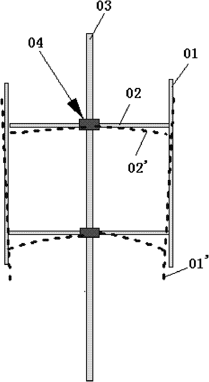
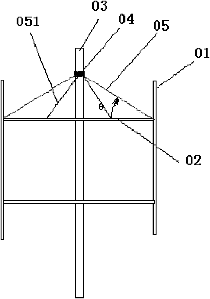
[0037] Such as figure 2 As shown, a wind wheel cable-stayed structure of a vertical axis wind power generator, wherein a wind wheel is arranged on a tower column 03 of the vertical axis wind power generator, and the wind wheel includes blades 01 and support bars 02, and several support bars 02 One end is fixed on the external rotor 06 of the generator set on the tower column 03, and the other end is fixed on the inner side of the columnar vertically arranged blade 01; the cable-stayed structure includes a cable-stayed bearing 04 and a cable 05; The cable-stayed bearing 04 is sleeved and fixed on the tower column 03 above the external rotor 06 of the generator. One end of the cable-stayed bearing 05 is connected to the external rotating part of the cable-stayed bearing, and the other end is connected to the external rotor 06 of the generator. The blades or support rods are connected. In this embodiment, the stay cables are connected to the connection points of the blade 01 an...


PUM


Abstract

The invention discloses a wind wheel cable-stayed structure of a wind driven generator with a vertical shaft. The wind wheel cable-stayed structure comprises a stay cable and a cable-stayed bearing; the cable-stayed bearing is sleeved and fixed on a part positioned above an external rotor of the generator on a tower column; and one end of the stay cable is connected with the cable-stayed bearing,and the other end of the stay cable is connected with a blade or a supporting rod which is connected with the blade. By utilizing the wind wheel cable-stayed structure, the restriction of the power transmission path that the weights of the wind wheels are transmitted to the tower column through the generator for the traditional wind wheel support structure is broken through, and the weights of the wind wheels are directly transmitted on the tower column. The reasonable and effective support of the large wind wheels is convenient to realize, the design and manufacturing cost of the large wind wheel support structure can be lowered, the frictional resistance can be reduced, the power generation efficiency can be improved, the fatigue stress can be reduced, the service life of the wind driven generator can be prolonged, and the quiet running property of the wind wheels can be increased, and the vibration of the wind wheels can be reduced.

Description

technical field [0001] The invention relates to a support structure for the weight of a wind rotor of a vertical axis wind power generator, in particular to a cable-stayed structure for directly pulling the weight of the wind rotor to a tower column. Background technique [0002] The vertical axis wind power generator includes a tower column, a wind rotor and a generator. The wind rotor includes a support rod and blades. One end of the support rod is connected to the tower column, and the other end is connected to the blade. dynamo. Under normal circumstances, the support rod is a cantilever beam, and the weight of the blade acts on the end of the cantilever beam. When the wind wheel rotates, the following problems are prone to occur: [0003] (1) In order to achieve the target power, medium-sized or larger wind turbines generally use larger wind rotors. Due to the excessive weight of the blades and support rods, the support rod 02 tends to deflect when the wind rotor rotat...

Claims


Application Information

Patent Timeline
IPC IPC(8): F03D3/06
CPCY02E10/74Y02P70/50
Inventor 蒋大龙许金泉
Owner NAT WIND ENERGY
Why Eureka
Try Eureka