
Prefabricated reinforced concrete beam and connection joint of reinforced concrete column and beam

A technology for reinforced concrete beams and connecting nodes, which is applied to structural elements, building components, and elongated structural components used for load-bearing, etc., and can solve the problem of insufficient integrity, bending resistance, shear resistance, and torsional strength of beam-column connection nodes , It is impossible to design problems such as prestressed tension, compression resistance, and shear resistance, so as to improve earthquake resistance and safety, reduce construction waste pollution, and ensure quality.

Inactive Publication Date: 2011-06-08
张吉华 +1
View PDF10 Cites 33 Cited by
  • Summary
  • Abstract
  • Description
  • Claims
  • Application Information

AI Technical Summary

Problems solved by technology

In this form of stress, the connection between the section steel joint and the steel bar becomes a weak point of tensile strength and shear resistance, which may easily lead to cracks at this weak point, or even breakage of the steel bar. become a strong node
Secondly, this structural reinforced concrete prefabricated beam, according to the current national building design code, can only be used for short beams with a span of ≤ 8 meters, and when the span of the beam is greater than 8 meters, prestressed tension must be designed, and the prefabricated beam of this structure is Prestressed tension cannot be designed, and it cannot be used for span > 8 meters long beams
[0003] In addition, the joints between beams and columns are also embedded with steel bars in reinforced concrete columns. The steel joints on the columns are fixed only by the reinforced concrete columns and the steel bars inside the columns. The anchoring strength is insufficient, and the reinforced concrete at the node is prone to cracks due to stress, which affects the strength, so that the integrity, bending resistance, shear resistance, and torsional strength of the entire beam-column connection node are insufficient, and become a weak node in the structure. Less than the existing national design specifications, affecting safety

Method used


Image

  • Prefabricated reinforced concrete beam and connection joint of reinforced concrete column and beam
  • Prefabricated reinforced concrete beam and connection joint of reinforced concrete column and beam
  • Prefabricated reinforced concrete beam and connection joint of reinforced concrete column and beam

Examples


Embodiment 1

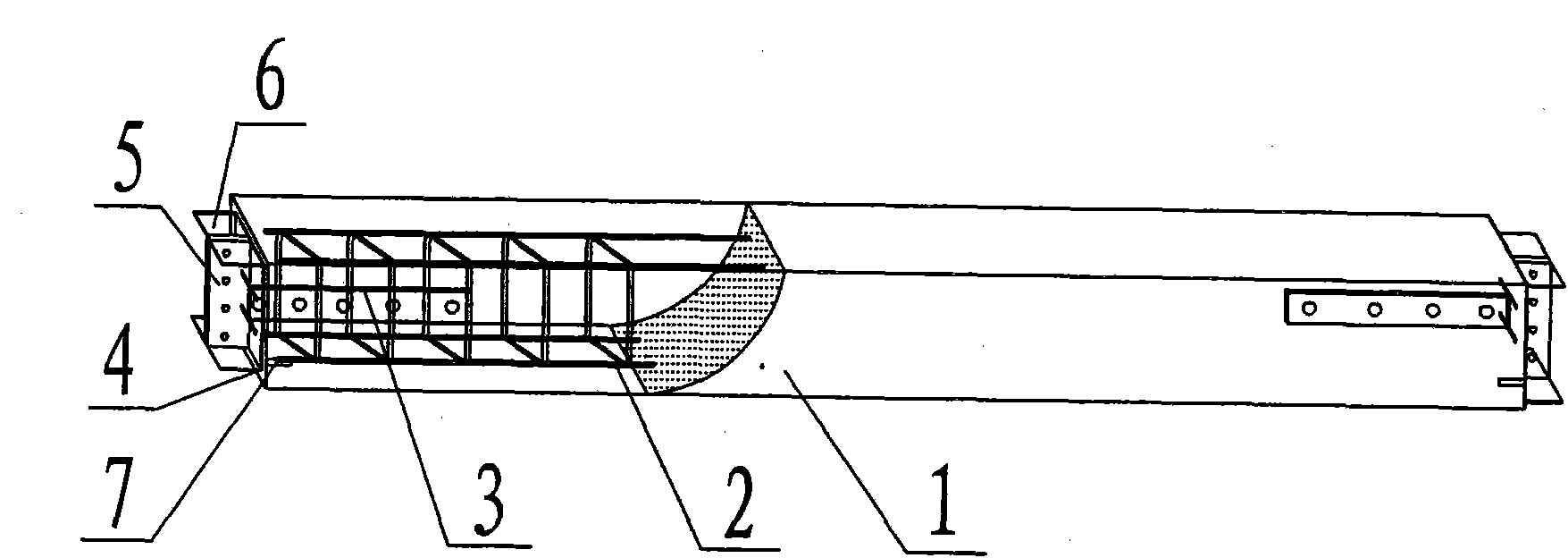
[0027] Embodiment 1: see figure 1 , The prefabricated reinforced concrete beam of the present invention includes the outer concrete 1, the inner reinforcement cage 2 designed according to the load, and the connecting steel joints at both ends. The shaped steel joints are transverse T-shaped steel, the section of the T-shaped end plate 4 is slightly smaller than the end face of the reinforced concrete beam, and shrinks in the inner end face of the reinforced concrete beam. The end plate has through holes corresponding to the main and auxiliary steel bars in each axial direction. The plate 4 forms a perforated plug welding connection, and the T-shaped handle is composed of an upper and lower horizontal plate 6 and a middle vertical plate 5 to form an I-shaped (H-shaped) structure connection portion, and the vertical plate 5 has a connection hole. There are short shear parts 7 inside the reinforced concrete on the end face of the T-shaped connecting steel, and a rigid steel membe...

Embodiment 2

[0028]Example 2: see figure 2 , As in Example 1, there are prestressed tension holes on the lower side of the reinforced concrete beam section axially (including through the T-shaped end plate 4), and built-in prestressed tension steel bars 8. This structural beam, one can reduce the beam section under the same load, and the other can be used for beams with a span greater than 8 meters.

Embodiment 3

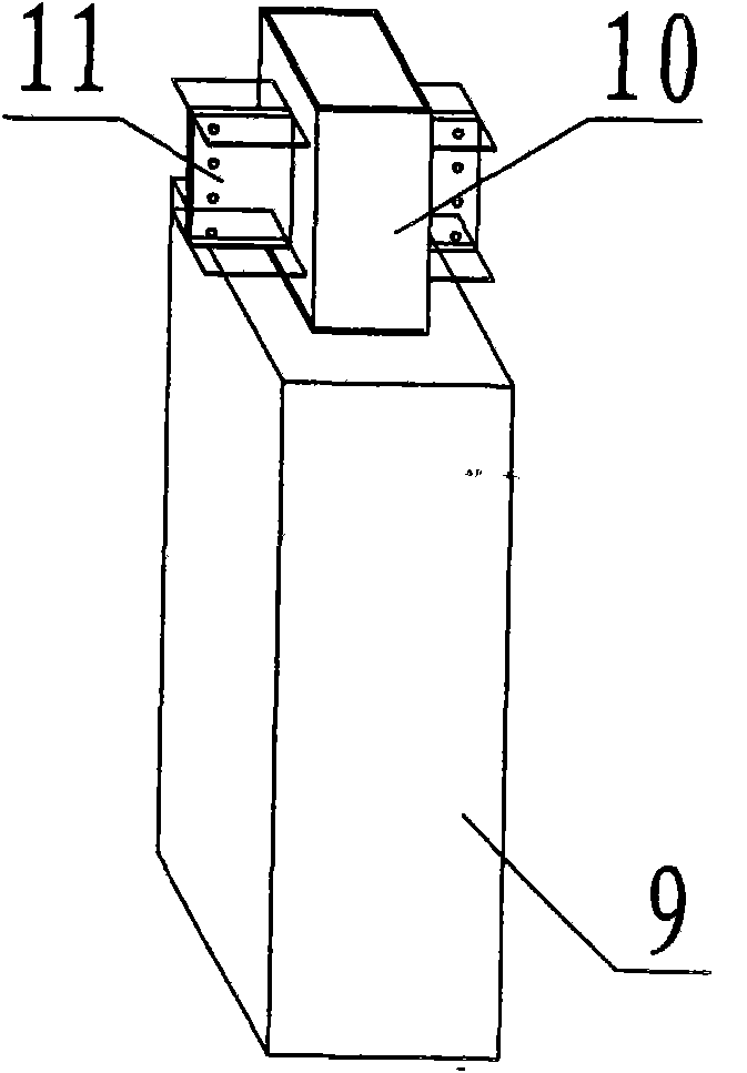
[0029] Embodiment 3: see image 3 , the connection node between the reinforced concrete column and the beam, including the reinforced concrete column 9 made of steel bars or steel pipes, in the area where it is connected to the beam, there is a built-in rigid steel pipe 10, and the steel pipe radially has a shear member (not shown in the figure) extending out, One side or two sides or three sides or four sides each have radially protruding I-shaped connecting section steel 11 with the same shape as the aforementioned beam connection part. After connecting with the beam, fill the package with concrete.


PUM


Abstract

The invention relates to the improvement of reinforced concrete beams for buildings and the connection joints of beams and columns, and is characterized in that transverse T-shaped structural section steel joints are disposed at the two ends of the reinforced concrete beam, wherein the T-shaped transverse end surface is at least equal to the cross section formed by the steel reinforcement cage in the beam, and at least in the reinforced concrete prefabricated beam, through holes are disposed at the corresponding positions of the main and auxiliary steel reinforcement; perforating plug welding or connection is formed by each main and auxiliary steel reinforcement perforating through the through holes; the reinforced concrete column connects the joints; an axial steel pipe is disposed at least in the cross section of the connecting part section of the column and the prefabricated beam; and a section steel joint extending outside the side surface of the column is disposed at the connecting surface of the steel pipe and the beam. Therefore, a strong joint structure is formed which is shear resistant, bending resistant, and has strong bearing capability; and also an elastic structure with a steel structural beam is formed which is anti-seismic and has good security. Prestress tension is built-in, so the invention is applicable to the production of large-span prefabricated reinforced concrete beams with a length more than 8 meters. The advantages of quick installation, high strength, elastic structure, and good security of steel structural beams are combined, and the cost is only 1 / 3 of steel structures, so the comprehensive benefit cost remains lower than that of reinforced concrete.

Description

technical field [0001] The present invention relates to the improvement of reinforced concrete beams used in buildings and the joints connected with columns, in particular to a prefabricated reinforced concrete beam with high joint strength, good shear resistance and torsion resistance and the joints connected with columns. First applied for further improvement and perfection of patent 200920283681.1. Background technique [0002] The middle beam of the building structure is usually a steel beam or a reinforced concrete (reinforced concrete) beam. Steel girders can be produced industrially, with convenient construction, high strength, and good earthquake resistance, but the cost is relatively high, and it is difficult to prevent fire and prevent corrosion. Reinforced concrete beams are divided into cast-in-place beams and prefabricated beams. Cast-in-place beams need formwork during construction, which results in large material loss and slow construction progress; prefabric...

Claims


Application Information

Patent Timeline
IPC IPC(8): E04C3/293E04B1/58
Inventor 张吉华张晨
Owner 张吉华
Learn More