Section-variable turbine
A turbine and cross-section technology, which is applied to gas turbine devices, mechanical equipment, engine components, etc., can solve the problems of limited gas flow adjustment range and low efficiency of tongue-shaped baffle superchargers, and achieves a simple control mechanism for air intake cross-section adjustment and control. The effect of easy control and broad market promotion value
- Summary
- Abstract
- Description
- Claims
- Application Information
AI Technical Summary
Problems solved by technology
Method used
Image
Examples
Embodiment 1
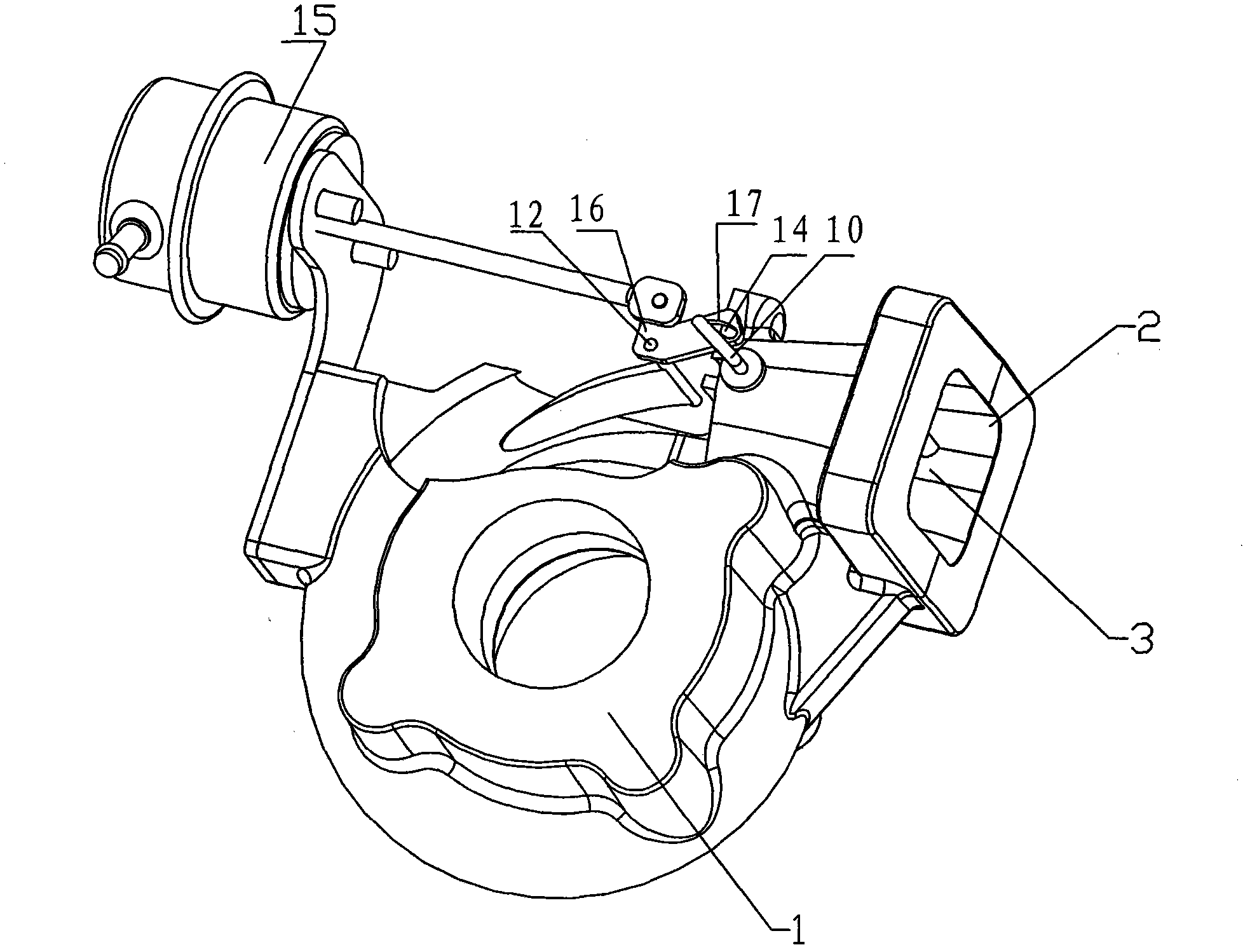
[0047] Embodiment 1, as attached figure 2 As shown, a variable cross-section turbine includes a volute 1, and the volute 1 is provided with an annular air passage 3, the annular air passage 3 has an air inlet 2, and the annular air passage 3 is provided with an intake section adjustment mechanism 17, The air intake section adjustment mechanism 17 is in driving connection with the actuator 15 .
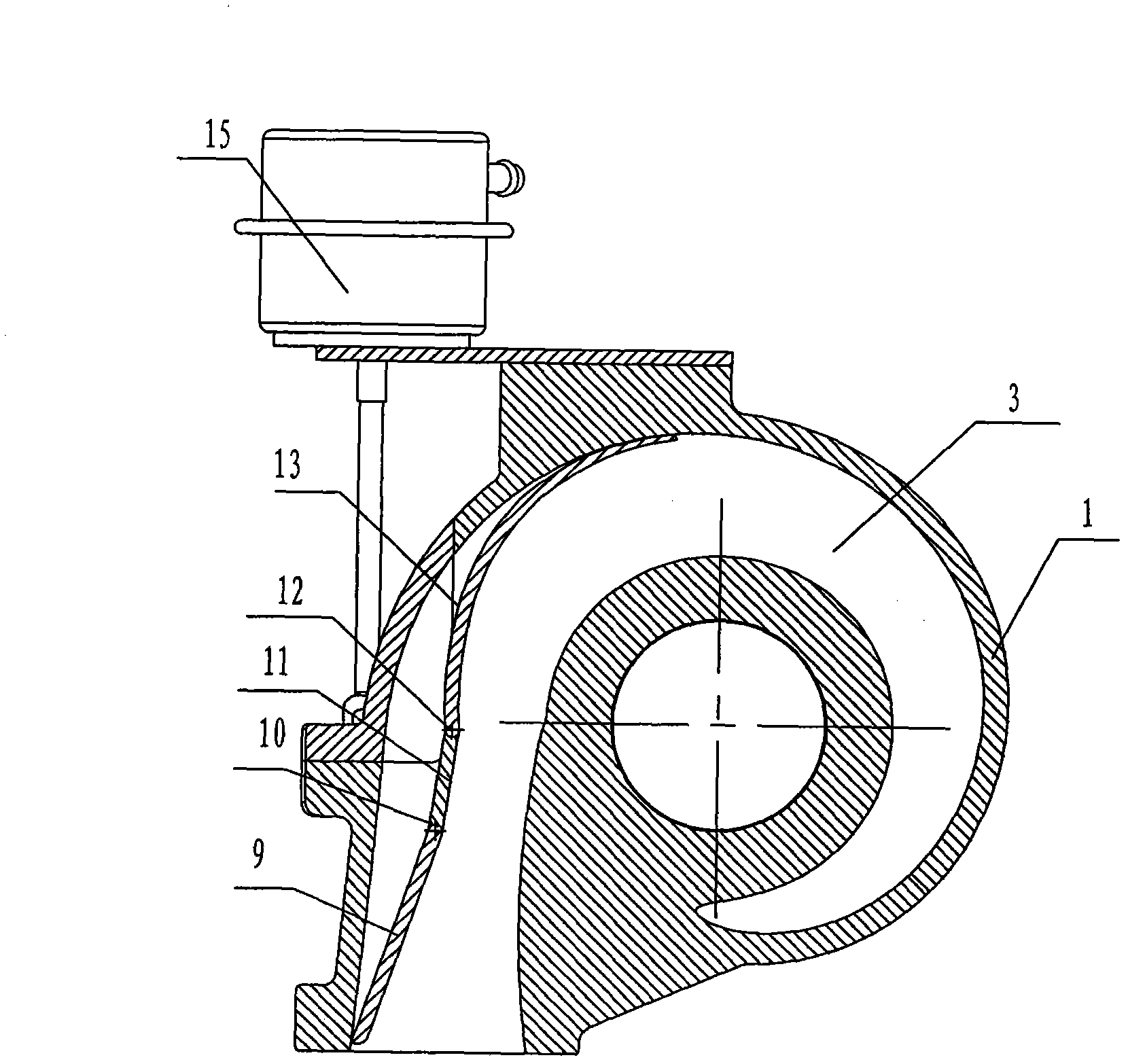
[0048] Such as image 3As shown, the air intake section adjustment mechanism 17 includes a fixed baffle 11 installed in the annular air passage 3 near the air inlet 2 , and the fixed baffle 11 is integrally cast with the volute 1 .
[0049] The fixed baffle 11, the movable straight plate 9 and the movable tongue-shaped baffle 13 are arranged along the axial direction of the annular flow channel 3, and are composed of a movable straight plate, a fixed baffle and a movable tongue-shaped baffle in order to reduce flow loss The shape line is similar to the shape line of the inner wall o...
Embodiment 2
[0059] Example 2, such as Figure 6 As shown, on the basis of Embodiment 1, in order to further expand the adjustment range of the intake air flow, the other end of the movable tongue-shaped baffle 13 is sequentially connected with a first movable tongue-shaped baffle 18 and a second movable tongue-shaped baffle. Movable tongue-shaped baffle 19, the end of the second movable tongue-shaped baffle 19 is located near the other end of the annular flow passage 3 relative to the air inlet 2, the first movable tongue-shaped baffle 18 and the second movable tongue-shaped baffle 19 are arranged along the axial direction of the annular flow channel 3 .
[0060] The first movable tongue-shaped baffle 18 and the second movable tongue-shaped baffle 19 are respectively installed on the volute 1 and are connected to the actuator 15 through transmission, so that the flow area can be adjusted in the flow area of the entire flow channel , to more effectively meet the supercharging requiremen...
Embodiment 3
[0062] Embodiment 3, after the air flow enters the volute, the flow inertia is used to perform work on the turbine, and the work performed by the air flow in the initial stage plays a very important role in the entire work process of the turbine. In order to make full use of the energy of the airflow in the initial stage of work, such as Figure 7 As shown, on the basis of Embodiment 1, the fixed baffle 11 is extended to a position in the annular air flow channel 3 close to the cross section of the air inlet 2 at an angle of 90°, and the installation position of the movable tongue-shaped baffle 13 is also It also moves backwards, and the installation method remains unchanged, which can prevent the airflow from expanding prematurely in the volute 1, so that the energy of the airflow can be more fully utilized. Especially when the engine is at a low speed, the supercharging pressure can be increased more effectively to meet the low-speed supercharging requirements of the engine....
PUM
 Abstract
Description
Claims
Application Information
 - R&D Engineer
- R&D Manager
- IP Professional
- Industry Leading Data Capabilities
- Powerful AI technology
- Patent DNA Extraction
Browse by: Latest US Patents, China's latest patents, Technical Efficacy Thesaurus, Application Domain, Technology Topic, Popular Technical Reports.
© 2024 PatSnap. All rights reserved.Legal|Privacy policy|Modern Slavery Act Transparency Statement|Sitemap|About US| Contact US: help@patsnap.com


