Combined control valve
A combined control and control port technology, which is applied in the direction of servo motor components, fluid pressure actuators, mechanical equipment, etc., can solve the problem of increasing the flow rate of the column hydraulic control check valve, increasing the flow rate of the main control reversing valve, and increasing the cost. Major and other issues
- Summary
- Abstract
- Description
- Claims
- Application Information
AI Technical Summary
Problems solved by technology
Method used
Image

Examples
Embodiment 1
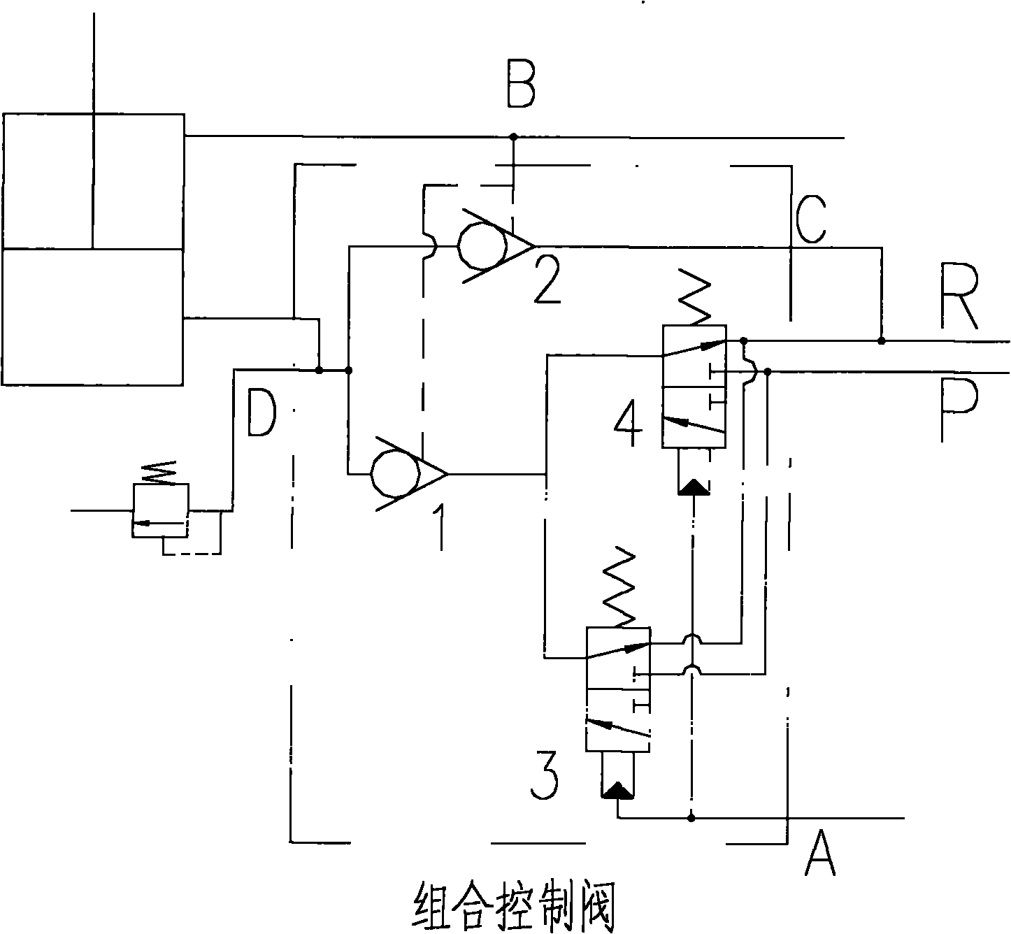
[0024] See attached figure 1 , which describes a preferred embodiment of the invention.
[0025] A combination control valve includes a reversing valve core 3, a reversing valve core 4, a hydraulic control check valve core 1 and a hydraulic control check valve core 2, and the hydraulic control check valve core 1 and the hydraulic control check valve core 2 The control port is connected to the control port of the hydraulically controlled one-way spool of the combined control valve, the control ports of the reversing spool 3 and 4 are connected to the control port of the reversing spool of the combined control valve, and the control port of the hydraulically controlled one-way spool 2 The liquid inlet end is connected to the liquid return path R through the quick bypass liquid return port of the combined control valve, the liquid outlet is connected to the rodless chamber of the hydraulic cylinder through the working port of the combined control valve, and the liquid inlet end o...
Embodiment 2
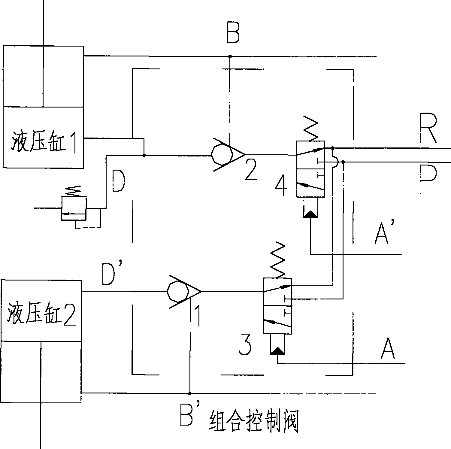
[0029] See attached figure 2 , which discloses another preferred embodiment of the present invention.
[0030] A combined control valve includes a reversing valve core 3, a reversing spool 4, a hydraulically controlled one-way valve core 1 and a hydraulically controlled one-way valve core 2, and the control ports of the reversing valve core 3 and the reversing valve core 4 are respectively connected The reversing spool control ports A and A' of the combined control valve, the control ports of the hydraulic control check spool 1 and the hydraulic control check spool 2 are respectively connected to the check spool control ports B' and B of the combined control valve, The liquid outlets of the hydraulic control check valve core 1 and the hydraulic control check valve core 2 are respectively connected to the two combined control valve working ports D and D' of the combined control valve, and the liquid inlet port of the reversing valve core 3 and the reversing valve The liquid i...
Embodiment 3
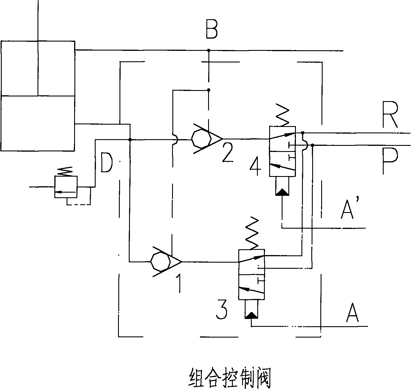
[0037] See attached image 3 , which discloses another preferred embodiment of the present invention.
[0038] The difference from Embodiment 2 is that the combined control valve only controls one hydraulic cylinder. Therefore, it is sufficient to set only one control port of the one-way spool and one working port of the combined control valve, and the liquid outlets of the two hydraulically controlled one-way spools are connected to the hydraulic cylinder through the working port of the combined control valve at the same time. Its specific working mode is similar to that of the combined control valve in Embodiment 2.
PUM
 Abstract
Description
Claims
Application Information
 - R&D
- Intellectual Property
- Life Sciences
- Materials
- Tech Scout
- Unparalleled Data Quality
- Higher Quality Content
- 60% Fewer Hallucinations
Browse by: Latest US Patents, China's latest patents, Technical Efficacy Thesaurus, Application Domain, Technology Topic, Popular Technical Reports.
© 2025 PatSnap. All rights reserved.Legal|Privacy policy|Modern Slavery Act Transparency Statement|Sitemap|About US| Contact US: help@patsnap.com