Liquid ejecting apparatus and method of controlling liquid ejecting apparatus

A technology of jetting device and liquid jetting head, which is applied in printing and other directions, can solve the problems of complicated ink control and larger size of recording head, and achieve the effects of reducing flying speed difference, preventing deviation of attachment position, and reducing crosstalk

Active Publication Date: 2011-05-25
SEIKO EPSON CORP
View PDF8 Cites 4 Cited by
  • Summary
  • Abstract
  • Description
  • Claims
  • Application Information

AI Technical Summary

Problems solved by technology

[0008] However, in the structure of the above-mentioned Patent Document 1, since the nozzle rows for ejecting the same type (same color) of ink are provided in multiple rows, there is a problem that the size of the recording head becomes larger accordingly and the control during ink ejection becomes complicated.

Method used


Image

  • Liquid ejecting apparatus and method of controlling liquid ejecting apparatus
  • Liquid ejecting apparatus and method of controlling liquid ejecting apparatus
  • Liquid ejecting apparatus and method of controlling liquid ejecting apparatus

Examples


Embodiment Construction

[0045] Hereinafter, embodiments for carrying out the present invention will be described with reference to the drawings. In addition, in the following examples, various limitations are made as preferred specific examples of the present invention, but the scope of the present invention is not limited to these forms unless there is a description that specifically limits the content of the present invention in the following description. In addition, below, an inkjet recording device (hereinafter referred to as a printer) will be described as an example of the liquid ejecting device of the present invention.

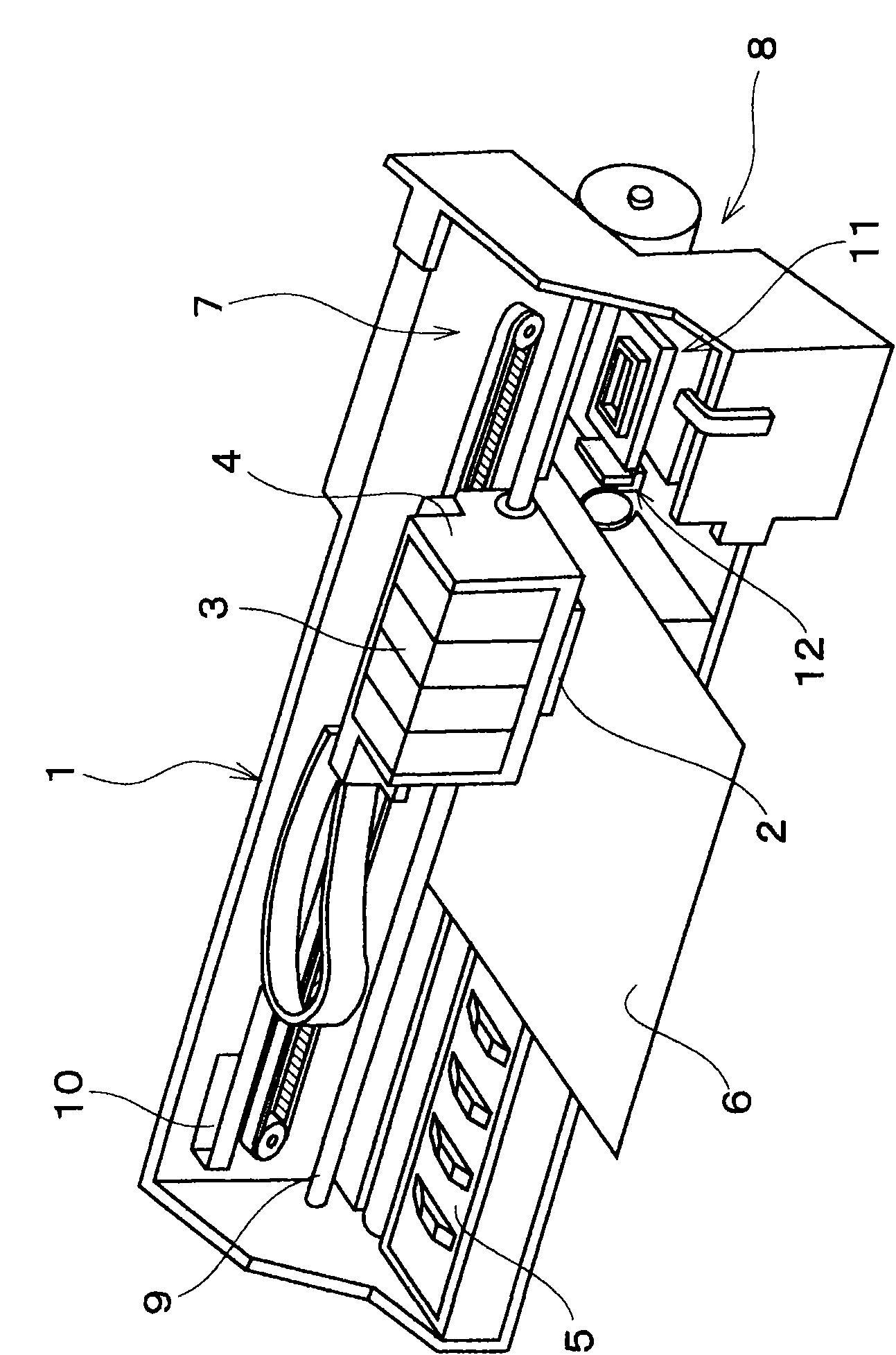
[0046] figure 1 It is a perspective view of the configuration of the printer 1 . This printer 1 generally includes: a carriage 4 on which a recording head 2 is installed as a liquid ejection head and an ink cartridge 3 is detachably installed; a platen 5 is arranged below the recording head 2; A carriage moving mechanism 7 (a kind of moving unit) that reciprocates in the ...


PUM


Abstract

The present invention relates to a liquid ejecting apparatus capable of preventing cross talk even when a liquid is ejected simultaneously from a plurality of nozzles adjacent to each other in the same nozzle group and to a method of controlling the liquid ejecting apparatus. The ejection driving pulse DP is a voltage waveform including a preliminary expansion section p1, an expansion hold section p2, a contraction section p3. The contraction section p3 includes a first contraction component p3a in which the potential is varied in the minus direction from the expansion potential VH, an intermediate hold component p3b in which an intermediate potential VM1, which is the termination potential of the first contraction component p3a, holds for a given time, and a second contraction component p3c in which the potential is varied in the minus direction from the intermediate potential. The hold time of the intermediate hold component is greater than 0 and 0.12 Tc or less. The potential of the intermediate hold component is in the range from 50% to 60% of the potential of the hold section.

Description

technical field [0001] The present invention relates to a liquid ejecting device such as an inkjet printer and a control method thereof, particularly a liquid ejecting device capable of controlling ejection of liquid by applying an ejection drive pulse to a pressure generating unit and a control method thereof. Background technique [0002] A liquid ejecting device is a device that includes a liquid ejecting head having a nozzle for ejecting a liquid, and ejects various liquids from the liquid ejecting head. As the representative of this liquid ejecting device, for example, can enumerate: have the ink-jet type recording head (hereinafter referred to simply as recording head) as liquid ejecting head, by injecting liquid ink from the nozzle of this recording head to recording paper etc. An image recording device such as an inkjet printer (hereinafter referred to as a printer) that forms dots after spraying and attaching a recording medium (attachment object) to record an image...

Claims


Application Information

Patent Timeline
Patent Type & Authority Applications(China)
IPC IPC(8): B41J2/14B41J2/07
CPCB41J2/04516B41J2/14274B41J2/04588B41J2/04525B41J2/04581
Inventor 松尾宽之
Owner SEIKO EPSON CORP
Why Eureka
Try Eureka