Eureka AIR delivers breakthrough ideas for toughest innovation challenges, trusted by R&D personnel around the world.

Pulsed gas jet impact drier

A technology of gas jet and drying machine, which is applied in application, food processing, food science, etc., can solve the problems of gas jet impact oven and gas jet impact drum, etc., and achieve stable operation, high hygienic index, and good consumption potential Effect

Inactive Publication Date: 2011-05-25
CHINA AGRI UNIV
View PDF6 Cites 14 Cited by
  • Summary
  • Abstract
  • Description
  • Claims
  • Application Information

AI Technical Summary

Problems solved by technology

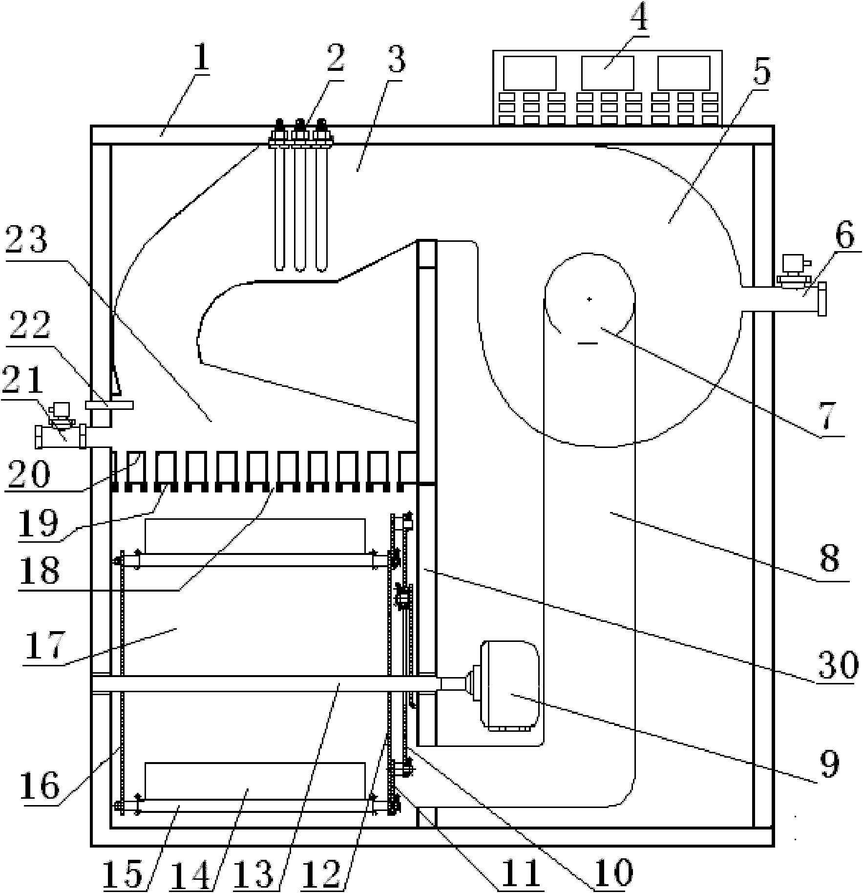
[0005] The purpose of the present invention is to overcome the problems of the gas jet impingement oven and gas jet impingement drum drying in the prior art, so as to effectively improve the drying efficiency, make the material dry more uniformly, and facilitate the replacement of the size and shape of the air outlet of the nozzle. To meet the requirements of drying different types of materials, a pulsating gas jet impact dryer is provided. The pulsating gas jet impact dryer is composed of an air circulation system, a material drying system, a temperature and humidity control system and a chassis 1. It is characterized in that the chassis 1 The middle partition 30 divides the inside of the cabinet into two parts, the left and the right. The air circulation system includes the fan 5, the fan outlet pipe 3, the air heating device 2, the air distribution chamber 23, the return air duct 8 and the jet plate. The fan 5 Place the upper part of the chassis 1 on the right side of the middle partition 30, the air outlet of the fan 1 is connected to the fan outlet pipe 3, and the fan outlet pipe 3 passes through the middle partition 30 and communicates with the air distribution chamber 23 on the upper part of the chassis 1 , the airflow heating device 2 is placed in the fan outlet pipe 3, the jet plate is horizontally placed in the lower part of the airflow distribution chamber 23, and is fixedly connected with the front side panel, rear side panel, left side panel and middle partition 30 of the chassis 1, and the return air The upper end of the pipe 8 communicates with the air inlet 7 of the fan, and the lower end passes through the middle partition 30 at the bottom of the cabinet 1 and communicates with the drying chamber 17;

Method used


Image

  • Pulsed gas jet impact drier
  • Pulsed gas jet impact drier
  • Pulsed gas jet impact drier

Examples


Embodiment Construction

[0024] The present invention will be further described in detail below in conjunction with the embodiments and the accompanying drawings. It should be emphasized that the following description is only exemplary and not intended to limit the scope of the invention and its application.

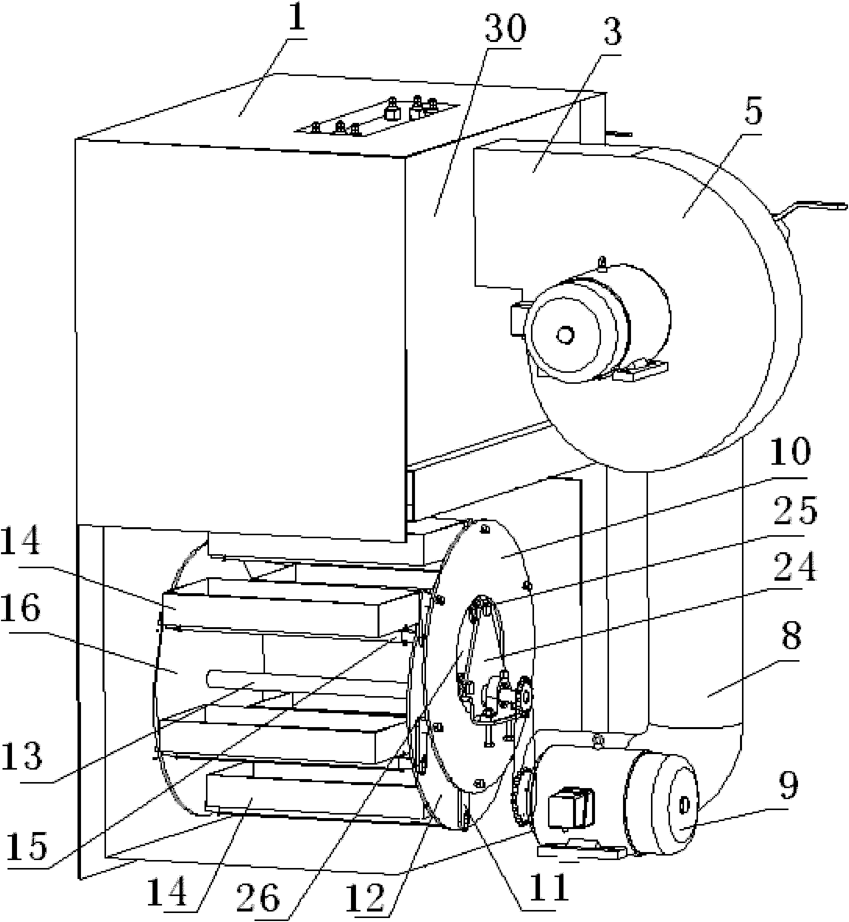
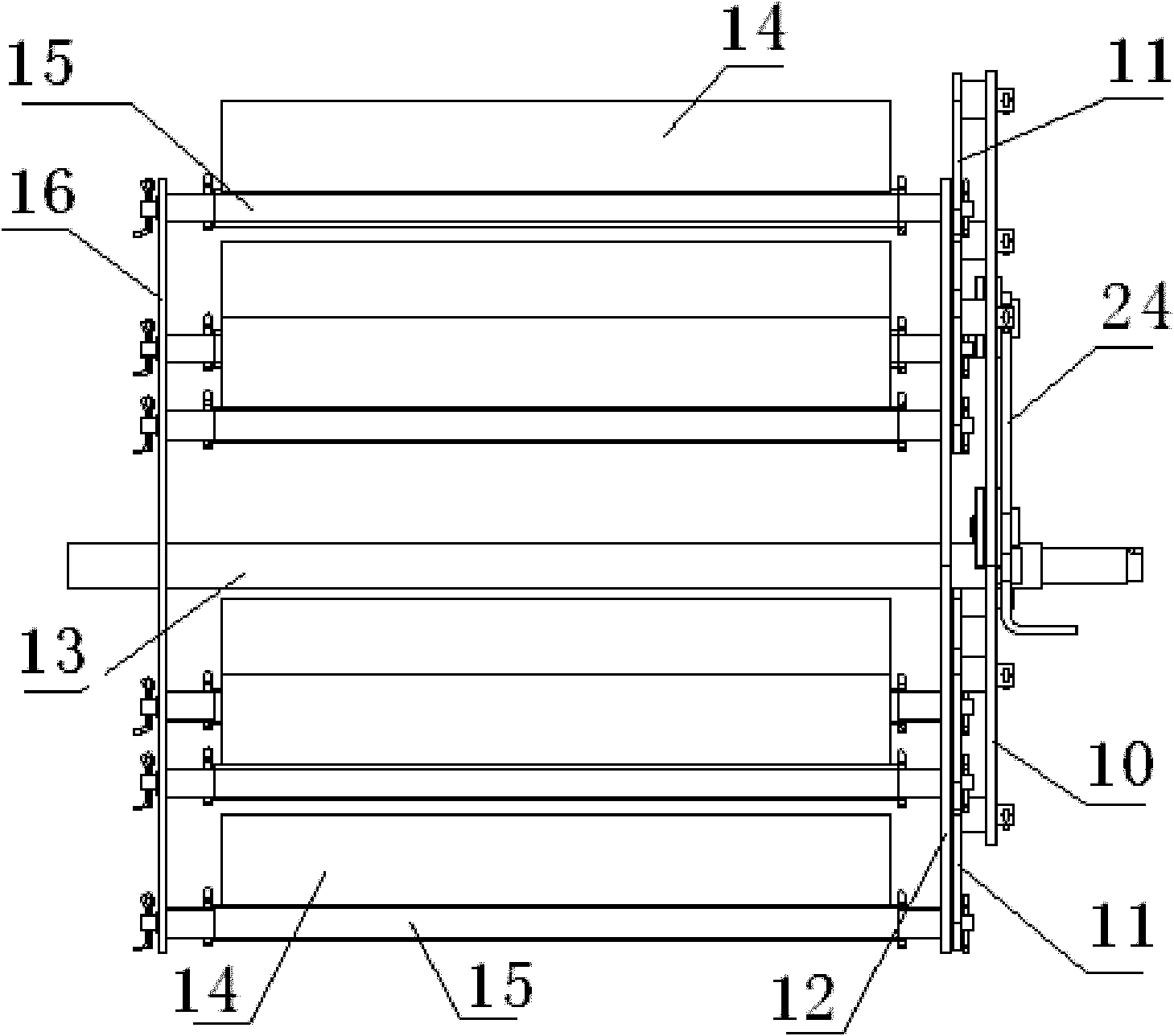
[0025] figure 1 with figure 2 It is a structural schematic diagram of an embodiment of a pulsating gas jet impingement dryer. The pulsating gas jet impingement dryer is composed of an air circulation system, a material drying system, a temperature and humidity control system and a chassis. The middle partition 30 in the cabinet 1 divides the inside of the cabinet into two parts, the left and the right, and the air circulation system includes the blower fan 5, the blower blower outlet duct 3, the airflow heating device 2, the airflow distribution chamber 23, the return air duct 8 and the jet plate. The fan 5 is placed on the upper part of the cabinet 1 on the right side of the middle partition...


PUM


Abstract

The invention belongs to the field of agricultural product processing machineries and relates to a pulsed gas jet impact drier. The pulsed gas jet impact drier consists of an air circulating system, a material drying system, a temperature and humidity control system and a case. A material frame of the drying system adopts a four-parallel rod mechanism; a material disc does horizontal rotary movement around a material frame shaft at a constant speed under the action of the four-parallel rod mechanism; and the bottom plane of the material disc is always vertical to the direction of the air flow jet by a jet plate. When the material disc is rotated to the top, the air flow impact applied to a material is maximum and then is gradually reduced; when the material disc is rotated to the bottom, the air flow impact applied to the material is minimum and then is gradually increased; and when the material disc is rotated to the top, the air flow impact applied to the material is maximum again and then the material is dried in a pulsing manner. Since a plurality of material discs do horizontal rotary movement around the material frame shaft at the same time, the loadage is increased and the phenomenon of uneven drying of the traditional gas jet impact drying device caused by relatively fixed positions of the material and a nozzle is avoided. The pulsed gas jet impact drier is applied to the drying of agricultural products, such as tomatoes, grapes, hot peppers and the like.

Description

technical field [0001] The invention belongs to the field of agricultural product processing machinery, in particular to a pulsed gas jet impact dryer. Background technique [0002] Gas jet impingement drying technology is a new drying technology that sprays heated gas with a certain pressure through a nozzle of a certain shape, and directly impacts the surface of the material. Due to the high velocity of the ejected gas and the short flow of the fluid, a very thin boundary layer is formed between the air flow and the surface of the material when it hits the material. Therefore, the convective heat transfer coefficient of gas jet impingement drying is several times or even an order of magnitude higher than that of general hot air drying, and has the characteristics of high efficiency and low energy consumption. Compared with traditional hot air drying technology, energy saving is about 20-30% ( Gao Zhenjiang. Experimental Research on Drying Mechanism and Parameters of Granu...

Claims


Application Information

Patent Timeline
IPC IPC(8): A23N12/08A23N12/12
Inventor 高振江王丽红张茜林海姚雪东
Owner CHINA AGRI UNIV
Why Eureka
Eureka Blog
Learn More