
Device for producing electrical energy from exhaust gas heat

A technology of equipment and electric energy, applied in the field of equipment for generating electric energy from exhaust heat, can solve the problems of expensive, inefficient, and unsuitable for mass production of thermoelectric generators, and achieve a stable and strong cooling structure or heat exchange components , Improving the effect of turbulent flow and compact structure

Active Publication Date: 2011-05-18
EMITEC EMISSIONSTECHNIK
View PDF3 Cites 10 Cited by
  • Summary
  • Abstract
  • Description
  • Claims
  • Application Information

AI Technical Summary

Problems solved by technology

But most of said thermoelectric generators are very expensive to manufacture and feature inefficient
Therefore, it is not suitable for mass production

Method used


Image

  • Device for producing electrical energy from exhaust gas heat
  • Device for producing electrical energy from exhaust gas heat
  • Device for producing electrical energy from exhaust gas heat

Examples


Embodiment Construction

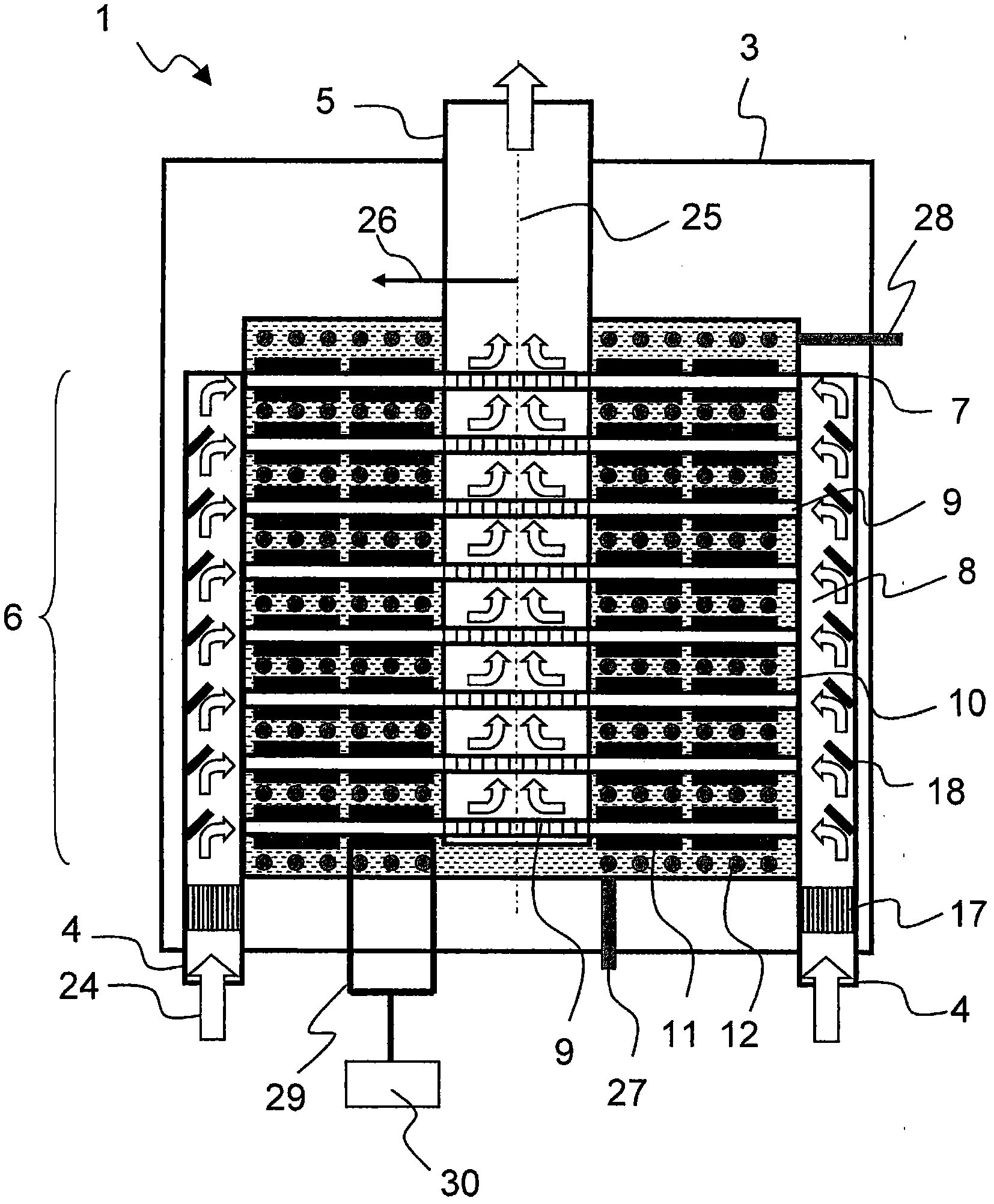
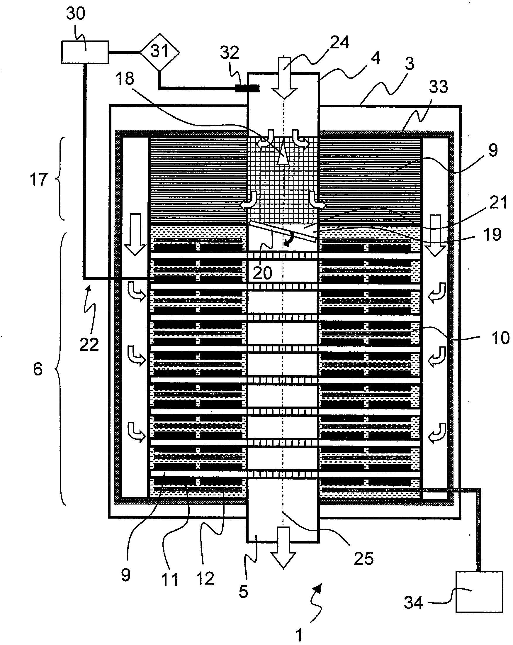
[0040] figure 1 A first embodiment of a device 1 according to the invention is shown for generating electrical energy from the exhaust gas of an engine 2 , not shown here. In the lower region, the device 1 has an annular channel which forms an exhaust gas inlet connection 4 . As indicated by the arrows, the entire exhaust gas flows into the generator 3 in a corresponding flow direction 24 . Initially the exhaust gas encounters a catalytic segment 17 , which is realized, for example, with a so-called honeycomb body in which a catalytically active coating is arranged. After passing through the catalytic section 17, the exhaust gas enters the heat exchange section 6, in which the exhaust gas is turned through 90° by means of guide structures arranged in the exhaust gas inlet connection 4 along the radial direction. flow inward. In this case, the exhaust gas is deflected into a plurality of flow paths 9 , whereby a flow distribution device 8 is realized on the housing surface. ...


PUM


Abstract

The present invention relates to a device (1) for producing electrical energy from the exhaust gas of an internal combustion engine (2), comprising a generator (3) with an exhaust gas inlet nozzle (4) and an exhaust gas exit nozzle (5) and at least one heat exchange section (6) therebetween, wherein at least one flow diverter (7) and flow distributor (8) is provided between the exhaust gas inlet nozzle (4) and the heat exchange section (6), and furthermore the heat exchange section (6) is designed with a plurality of flow paths (9) perpendicular to the exhaust gas inlet nozzle (4), said pathsable to be assigned to a plurality of heat exchange assemblies (10), wherein furthermore at least a section of the heat exchange assembly (10) is designed with at least one thermoelectric element (11) and one cooling device (12) and the at least one thermoelectric element (11) is connected to the cooling device (12) undetachably.

Description

technical field [0001] The invention relates to a device for generating electrical energy from the exhaust gas of an engine by means of a generator. This refers in particular to generators for converting the thermal energy of the exhaust gas into electrical energy, so-called thermoelectric generators (thermoelectric generators). Background technique [0002] The exhaust gas of a motor vehicle engine contains heat energy which can be converted into electrical energy by means of a thermoelectric generator, for example to fill batteries or other energy stores or to directly supply consumers with the required energy. As a result, energy is available over a large area for the operation of the motor vehicle. [0003] Such thermoelectric generators usually have a plurality of thermoelectric conversion elements. A thermoelectric material is a material that efficiently converts thermal energy into electrical energy (Seebeck effect) and vice versa (Peltier effect). The "Seebeck eff...

Claims


Application Information

Patent Timeline
Patent Type & Authority Applications(China)
IPC IPC(8): F01N3/20F01N3/28F01N5/02H01L35/30H01L35/32H10N10/13H10N10/17
CPCF01N5/025F01N3/2889F01N3/2053H01L35/32F01N2410/02H01L35/30Y02T10/16Y02A50/20Y02T10/12H10N10/13H10N10/17
Inventor R·布吕科J·霍格森S·林贝克A·沙茨
Owner EMITEC EMISSIONSTECHNIK
Learn More