
Structure for reducing unbalance of wound motor slip ring

A winding type, balanced technology, applied in asynchronous induction motors, electrical components, electromechanical devices, etc., can solve the problems of uneven weight distribution of conductive rods, hidden dangers of motor operation, etc., to achieve simple structure, reduce unbalance, and effect. obvious effect

Active Publication Date: 2011-05-18
SEC ELECTRIC MACHINERY
View PDF4 Cites 3 Cited by
  • Summary
  • Abstract
  • Description
  • Claims
  • Application Information

AI Technical Summary

Problems solved by technology

[0002] The slip ring is one of the basic components of the wound wire asynchronous motor. For the wound wire motor, especially the outer slip wound wire motor, due to the uneven weight distribution of the conductive rod on the slip ring, it often causes the brush holder of the motor and even the whole motor to generate a lot of damage. Large vibration, which brings hidden dangers to the operation of the motor

Method used


Image

  • Structure for reducing unbalance of wound motor slip ring
  • Structure for reducing unbalance of wound motor slip ring
  • Structure for reducing unbalance of wound motor slip ring

Examples


Embodiment Construction

[0016] The specific embodiments of the present invention will be further described below in conjunction with the drawings.

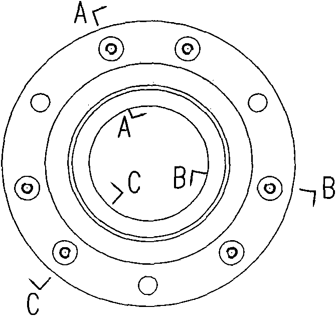
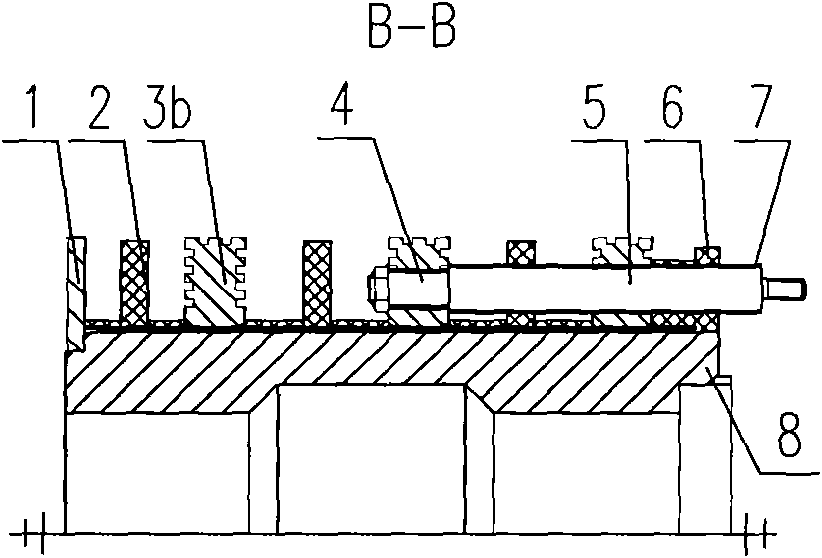
[0017] Such as Figure 1~4 As shown, the present invention includes a circular plate 1, three insulating plates 2, three slip rings 3a, 3b, 3c, six hexagon nuts 4, three conductive rods 5, an insulating washer 6, six insulating tubes 7 and A sleeve 8. The circular plate 1, the insulating plate 2, the slip rings 3a, 3b, 3c and the insulating washer 6 are sequentially sleeved on the sleeve 8. The three conductive rods 5 pass through the corresponding insulating washer 6, the insulating plate 2 and the slip rings 3a, 3b, 3c: Use hexagon nuts 4 to fix the three slip rings 3a, 3b, 3c, respectively, and sleeve the insulating tube 7 on the corresponding conductive rod 5.

[0018] Such as Figure 5-7 As shown, in the three slip rings 3a, 3b, 3c, two of the slip rings 3a, 3b are drilled in the vicinity of each pair of holes 9 for conducting rods, and three additiona...


PUM


Abstract

The invention relates to a structure for reducing the unbalance of a wound motor slip ring. The structure comprises a circular board, three insulating boards, three slip rings, six hexagonal nuts, six conducting rod, an insulating gasket, six insulating tubes and a sleeve. All the slip rings, the insulating boards, the circular board and the insulating gasket are sleeved on the sleeve; the conducting rods run through the corresponding slip rings, the insulating boards and the insulating gasket and are fixed on the slip rings by the nuts; the insulating tubes are sleeved on the corresponding conducting rods; weight reduction holes for reducing the weight are drilled at the position, near a hole for penetrating the conducting rods, of two of the three slip rings; and the number and the sizes of the weight reduction holes, near the hole for penetrating the conducting rods, on one slip ring are the same as the number and the sizes of the weight reduction holes on the other slip ring. The structure for reducing the unbalance of the wound motor slip ring is simple and compact, and is remarkable in interaction effect; under the conditions of not changing the material of the structure and guaranteeing the safety and the reliability of the motor, the unbalance of the slip rings is reduced by adding the weight reduction holes on the slip rings so as to prevent vibrations caused by the slip rings in the operation of the motor.

Description

Technical field [0001] The present invention relates to a rotor slip ring structure of a motor, in particular to a rotor slip ring structure of a three-phase asynchronous winding motor. Background technique [0002] The slip ring is one of the basic components of the winding type asynchronous motor. For the winding type motor, especially the outer sliding winding motor, due to the uneven weight distribution of the conductive rods on the slip ring, it often results in the motor brush holder and even the entire motor. Large vibrations bring hidden dangers to the operation of the motor. Summary of the invention [0003] The purpose of the present invention is to overcome the above shortcomings and provide a structure that reduces the unbalanced amount of the winding motor slip ring. Without changing the structural material, under the premise of ensuring the safety and reliability of the motor, through the slip ring Add weight-removing holes on the ring to reduce the imbalance of the...

Claims


Application Information

Patent Timeline
Patent Type & Authority Applications(China)
IPC IPC(8): H02K17/22
Inventor 吕莹
Owner SEC ELECTRIC MACHINERY
Learn More