Eureka AIR delivers breakthrough ideas for toughest innovation challenges, trusted by R&D personnel around the world.

Screwdriver

A screwdriver and gear technology, applied in the field of screwdrivers, can solve the problems of unsatisfactory structural reliability of the ratchet, inability to twist, spinning in situ, and decreased efficiency of screwing, etc., so as to achieve a reasonable and compact overall structure design, save time, and increase the number of new additions. The effect of the function

Inactive Publication Date: 2011-05-18
SHAOXING EVERPOWER TOOLS
View PDF1 Cites 16 Cited by
  • Summary
  • Abstract
  • Description
  • Claims
  • Application Information

AI Technical Summary

Problems solved by technology

The advantage is that the clutch state of the brake block and the bayonet is controlled by the arc-shaped slider. The ratchet screwdriver can be turned clockwise or counterclockwise, which is convenient to use. The disadvantage is that the traditional ratchet structure design uses the screwdriver handle to rotate in reverse During the process, the screw cannot be turned. Wait until the wrist is turned in place, and then turn the screw forward, so that turning the screw by hand is more convenient and light. Unfortunately, due to idling, the efficiency of turning the screw will inevitably decrease. Further improve the design; in addition, this traditional ratchet screwdriver often causes the screwdriver to drive the screw to rotate during the idling process during use, resulting in the screw not being able to be screwed, and turning in situ, indicating that the reliability of this ratchet structure is not ideal, and it is also necessary to Improve

Method used


Image

  • Screwdriver
  • Screwdriver
  • Screwdriver

Examples


Embodiment Construction

[0030] The present invention will be further described in detail below in conjunction with the accompanying drawings and embodiments.

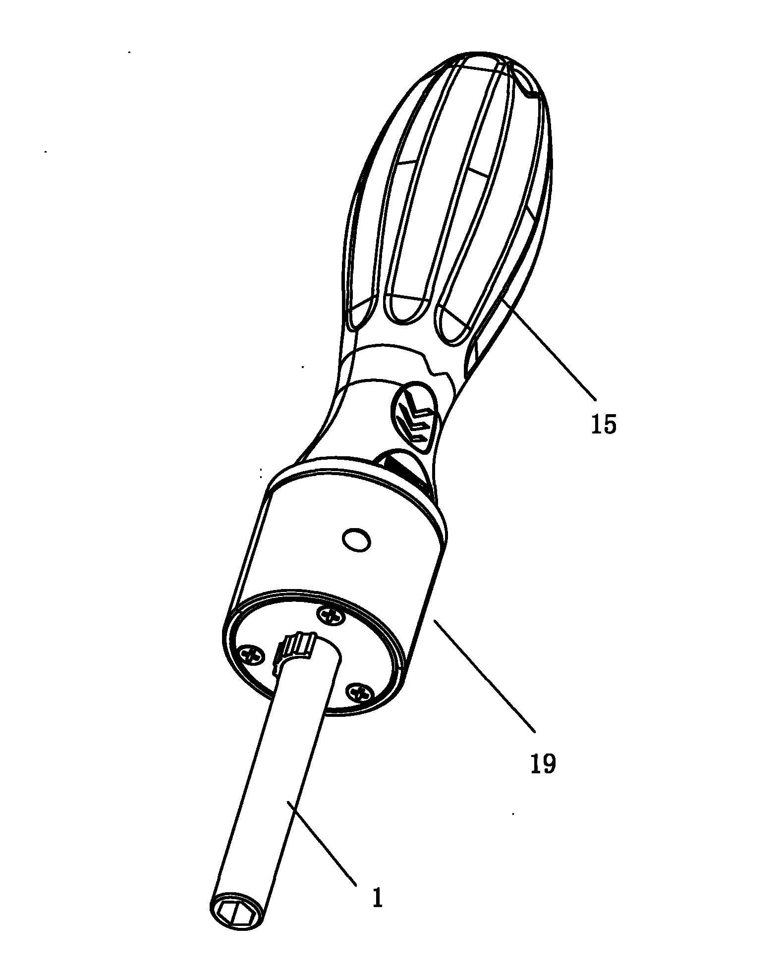
[0031] As shown in the figure, a screwdriver includes: a handle 15, which is usually made of plastic, and is a part for manual operation to provide a source of power; a gear device 19 is arranged at the front end of the handle 15 to realize rotation. The positive and negative rotation of the tool head 1 usually allows the screwdriver head 1 of the locking screw to rotate clockwise or counterclockwise, and the efficiency of locking the screw can be improved through the function of idling, without the need to turn the power driver (hand) back one by one Original position; screwdriver head 1, one end is connected with gear unit 19, and the other end is detachably inserted with screwdriver head, is convenient to insert the screwdriver head of various specifications; The key point of its invention is that gear unit 19 is A gear device with new func...


PUM


Abstract

The invention relates to a screwdriver comprising a handle, a gear device and a screwdriver head. The screwdriver is characterized in that the gear device at least comprises a device shell, a main driving gear, a front circular gear, a rear circular gear, a secondary driving gear group, a spring mounting pin, a front gear block, a rear gear block and a steering button, wherein the front circular gear and the rear circular gear are arranged corresponding to a homocentric shaft, lateral ring gears are distributed on the opposite circular surfaces, the inner rings of the front circular gear and the rear circular gear are inner gear rings; a gearwheel of the secondary driving gear group is engaged with the main driving gear, coaxial pinions in the secondary driving gear group are respectively engaged and connected with the front circular gear and the rear circular gear; the spring mounting pin penetrates into the rear end of the screwdriver head, the front and the back of the spring mounting pin are respectively provided with openings so that the spring and the steel beads can be sequentially filled in the openings; the front gear block and the rear gear block are respectively mounted in containing opening at the front and the back of the rear segment of the screwdriver head, the inner surfaces of the front gear block and the rear gear block abut on and match with respectively steel beads, the outer surfaces of the front gear block and the rear gear block keep contact with the inner gear rings of the front circular gear and the rear circular gear, and the steering button is mounted on the screwdriver head. The invention has more reasonable and practical structure and improves the efficiency.

Description

technical field [0001] The invention relates to a screwdriver. Background technique [0002] Along with the continuous progress of science and technology and the continuous improvement of people's living standards, various screwdrivers that can replace the screwdriver head have been widely used, and scientific and technical personnel have developed various screwdrivers for this reason. [0003] For example, the Chinese patent with the patent application number 200620103975.8 discloses a combined ratchet screwdriver, including a handle and a ratchet device fixed on the handle. The ratchet device is provided with an axial central through hole for installing the screwdriver bit. Including: a connection seat, the connection seat is fixedly connected with the handle, and its outer circumference is provided with a slide groove, and two accommodating grooves are arranged axially symmetrically on the outside; a sleeve, the sleeve is connected with the connection seat in rotation, an...

Claims


Application Information

Patent Timeline
Patent Type & Authority Applications(China)
IPC IPC(8): B25B15/02B25B17/00B25B23/00
Inventor 徐卫锋格兰·罗宾逊
Owner SHAOXING EVERPOWER TOOLS
Why Eureka
Eureka Blog
Learn More