
Double-screw rod kneading device

A kneader and twin-screw technology, applied in mixers, mixers with rotary stirring devices, mixer accessories, etc., to achieve the effects of ensuring axial positioning, simple structure, and widening use conditions

Inactive Publication Date: 2011-05-18
DALIAN UNIV OF TECH
View PDF4 Cites 6 Cited by
  • Summary
  • Abstract
  • Description
  • Claims
  • Application Information

AI Technical Summary

Problems solved by technology

[0005] The technical problem to be solved in the present invention is to invent a twin-screw kneader device to meet the technological needs of different types of twin-screw kneaders in view of the technical defects of existing twin-screw kneading equipment

Method used


Image

  • Double-screw rod kneading device
  • Double-screw rod kneading device
  • Double-screw rod kneading device

Examples


Embodiment approach 1

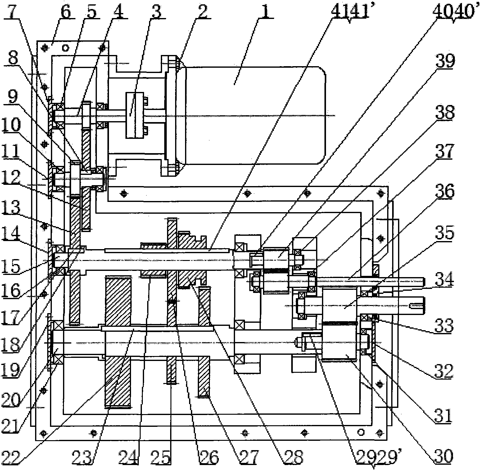
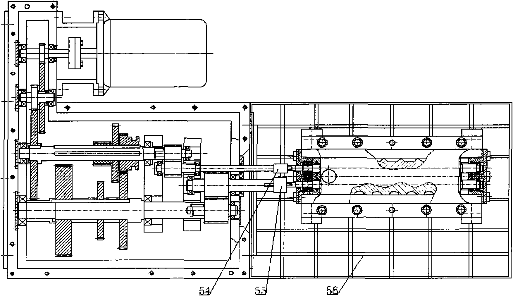
[0023] like figure 1 As shown, the motor 1 is connected with the first-stage gear shaft 4 of the gearbox input shaft through a coupling 3 to transmit the motive force, and the first-stage gear shaft 4 and the second-stage gear shaft 9 are meshed through the first-stage large gear 12, The second-stage gear shaft 9 and the sliding gear shaft 15 are meshed through the second-stage large gear 13; The sliding gear set can be adjusted so that the sliding gear set meshes with the mating gear on the power shaft 20 to transmit power. Adjust the 1:1 gear gear 26 in the sliding gear set to the position where it meshes with the 1:1 gear mating gear 25 through the shift lever, the specific position can be seen figure 1 The position of the slipping gear set. The sliding gear shaft 15 and the power shaft 20 are respectively connected to the other two transition shafts by splines—a high-speed transition shaft 39 and a low-speed transition shaft 30; The gears are meshed, and the power is tr...

Embodiment approach 2

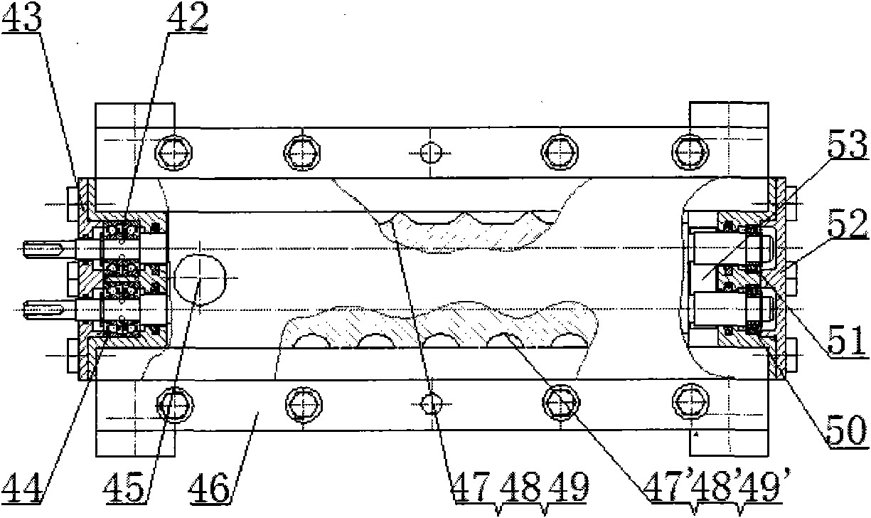
[0025] Adjust the 1:2 gear pinion gear 28 in the sliding gear set to the position of mating and meshing with the 1:2 gear gear gear 27 through the shift lever, and finally transmit the power to the second gear with a gear ratio of 1:2. The male screw rotor 48 and the second female screw rotor 48', the material enters the kneader from the feed port 45 on the barrel 46, through the rotation of the twin-screw rotors, and after being fully stirred and extruded, the material is discharged from the discharge port 53 discharge.

Embodiment approach 3

[0027] The 1:4 gear pinion gear 24 in the sliding gear set is adjusted to the position of mating and meshing with the 1:4 gear gear gear 22 through the shift lever, and finally the power is transmitted to the third gear gear with a gear ratio of 1:4. The male screw rotor 49 and the third female screw rotor 49', the material enters the kneader from the feed port 45 on the barrel 46, through the rotation of the twin-screw rotors, and after being fully stirred and extruded, the material is discharged from the discharge port 53 discharge.

[0028] The invention can quickly replace different screw rotors according to different processing requirements, and greatly improves the production efficiency of the twin-screw kneading equipment.


PUM


Abstract

The invention provides a double-screw rod kneading device, relates to a kneading device, and is applied to the production fields such as oil, chemical industry, rubber, plastics, pharmacy, food, etc. The double-screw rod kneading device comprises a motor, a rack, a gear box, a cylinder and a screw rod rotor mechanism. The prime power offered by the motor is subjected to speed reduction and power division by the gear box and is finally transmitted to a double-screw rod rotor in the kneading device, so that the rotation of the device reaches a work status. The gear box of the kneading device mainly comprises a two-stage reducer drive mechanism and a sliding gear set with three gears such as 1: 1, 1: 2 and 1: 4; and in the cylinder and the screw rod rotor mechanism, the two screw rod rotors which are meshed with each other are arranged in the cylinder, and the screw rod rotor mechanism comprises three male screw rod rotors and three female screw rod rotors. The double-screw rod kneading device is simple and compact in structure, so that the different outputs can be realized by adjusting the gears of the sliding gear set according to the different head number ratios of the screw rod rotors, the use requirement of the double-screw rod rotor with different head number ratios can be met, and the use range of the double-screw rod kneading device is widened.

Description

technical field [0001] The invention belongs to a kneading device, in particular to a twin-screw kneading device, which is suitable for production fields such as petroleum, chemical industry, rubber, plastic, pharmacy and food. Background technique [0002] Kneader is widely used in chemical, rubber, plastic, pharmaceutical, food and other industries. It is a high-performance mechanical equipment for mixing, stirring and plasticizing high-viscosity and ultra-high-viscosity substances. Especially in the past 30 years, with the rapid development of the polymer industry, more than 85% of the polymerization reactors, which are the core equipment for producing polymer materials, are stirring equipment. The research and development of efficient polymerization reactors will have a strong impetus to the development of kneading and stirring equipment. In order to meet the needs of high-quality and high-performance engineering plastic products, a large number of kneading equipment fo...

Claims


Application Information

Patent Timeline
Patent Type & Authority Applications(China)
IPC IPC(8): B01F7/02B01F15/00
Inventor 魏静孙旭建孙伟
Owner DALIAN UNIV OF TECH
Learn More