Light-emitting diode (LED) display system and method having pulse scattering mode

A display system and LED lamp technology, applied in static indicators, lighting devices, light sources, etc., can solve the problems that the distribution of brightness information cannot be guaranteed to be very uniform, cannot be scattered, and there is no algorithm, etc., to achieve uniform distribution of brightness information and simple algorithm Clear, reduced flickering effects

Inactive Publication Date: 2011-05-11
HANGZHOU XINXUN TECH CO LTD
View PDF4 Cites 33 Cited by
  • Summary
  • Abstract
  • Description
  • Claims
  • Application Information

AI Technical Summary

Problems solved by technology

[0015] The above-mentioned pulse breaking method has the following defects: when there are many bits, because there is no clear algorithm to follow, the splitting is relatively random, and it cannot guarantee that the brightness information after splitting is evenly distributed
For example, in the commonly used LED display system, when the grayscale is 16bit, the effective display time corresponding to the 16-bit grayscale data bits from high to low are: 64*512T, 32*512T, 16*512T, 8*512T . 32, 16, 8, 4, 2 times, a total of 126 displays are required, and the lower 10 bits of the gray value are not split, a total of 136 displays; how to arrange the order of these 136 displays can make the brightness information more uniform, The above dispersing scheme is not explained; therefore, in the commonly used LED display system, the pulse dispersing cannot be performed according to the above scheme when the gray value is 16bit

Method used


Image

  • Light-emitting diode (LED) display system and method having pulse scattering mode
  • Light-emitting diode (LED) display system and method having pulse scattering mode
  • Light-emitting diode (LED) display system and method having pulse scattering mode

Examples


Embodiment Construction

[0053] The content of the present invention will be further described below in conjunction with the LED display system.

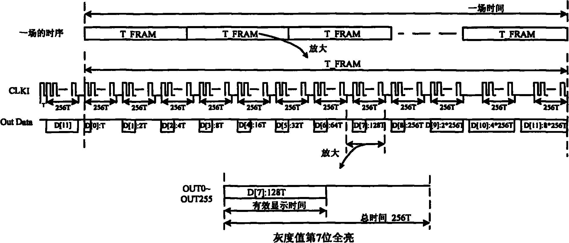
[0054] figure 1 It is a schematic diagram of the timing of the traditional LED pulse display mode. like figure 1 As shown, in the shown T_FRAM time, a total of 12 times of display and shift are required, and the total time of T_FRAM is about 23*256T; in this T_FRAM, the brightness of a certain LED light is calculated as follows:

[0055] D[0]*1T+D[1]*2T+D[2]*4T+D[3]*8T+D[4]*16T+D[5]*32T+D[6]*64T+D [7]*128T+D[8]*256T+D[9]*2*256T+D[10]*4*256T+D[11]*8*256T.

[0056] It can be seen from the figure that the luminance information of the high bits of the 12-bit grayscale value will be displayed intensively. For example, the effective display time of the highest bit accounts for more than 1 / 3 of the total time T_FRAM, which will make the brightness of the human eye very uncomfortable. Uniform, resulting in full-screen color is not soft. The above-mentioned met...


PUM


Abstract

The invention relates to an Light-emitting diode (LED) display system having a pulse scattering mode, which comprises an LED controller and a plurality of LED unit plates which are sequentially connected in series, wherein each LED unit plate respectively comprises an LED driving plate and a plurality of LED lamps; and the LED controller sends out data signals and control signals. An array D[i][0:(H-1)] represents the H-bit grey scale value of one LED lamp driven by a certain i end, D[i][0] represents the lowest-order bit value of the H-bit grey scale, and the D[i][0:(H-1)] is resolved into ahigh-order bit and a low-order bit, wherein the effective display time of the high-order bit is reduced to 1 / 2<n> before being wholly repeated for 2<n> times, namely 2<n>*D[i][n:(H-1)]+D[i][0:(n-1)];scan display is sequentially carried out on the D[i][n:(H-1)] for 2<n> times to enable the display to be more uniform, 2<n> remainders R are used to represent the low-order bit D[i][0:(n-1)], and theremainder bit R and the last bit D[i][n] of the high-order bit D[i][n:(H-1)] have an equivalent width in effective display time; and the formula of the scattering scheme can be shown as follows: D[0:m]=2<n>*(D[n:m]+R). In the mode, brightness can be more uniform, twinkling can be obviously reduced, and different resolution modes can meet application requirements of different systems.

Description

technical field [0001] The invention relates to the technical field of LED display, in particular to an LED display system with a pulse breaking method. Background technique [0002] The luminescent material of the LED display is a light-emitting diode. The forward volt-ampere characteristics of the light-emitting diode are roughly the same as those of ordinary diodes. There is no current before the opening point of the voltage. The volt-ampere characteristic of the LED is approximately linear from the conduction to the safe maximum current. That is, in this region, the luminous intensity of the LED is approximately proportional to its current intensity, and the brightness of the light-emitting diode can be controlled by controlling the current. [0003] Generally speaking, there are usually two methods to control the brightness of LEDs: current control method and conduction time control method. The current control method is to control the brightness by adjusting the forwa...

Claims


Application Information

Patent Timeline
Patent Type & Authority Applications(China)
IPC IPC(8): G09G3/32H05B37/02
CPCY02B20/40
Inventor 斯斐霞赵启永陈日仪
Owner HANGZHOU XINXUN TECH CO LTD
Why Eureka
Try Eureka