
Source driver and charge sharing function controlling method thereof

A source driver, charge sharing technology, applied in the direction of instruments, static indicators, etc., can solve the problem of source driver SD operating temperature rise, etc., to achieve the effect of power consumption and operating temperature reduction

Inactive Publication Date: 2011-05-11
HIMAX TECH LTD
View PDF0 Cites 5 Cited by
  • Summary
  • Abstract
  • Description
  • Claims
  • Application Information

AI Technical Summary

Problems solved by technology

This unanticipated situation will cause the operating temperature of the source driver SD to increase

Method used


Image

  • Source driver and charge sharing function controlling method thereof
  • Source driver and charge sharing function controlling method thereof
  • Source driver and charge sharing function controlling method thereof

Examples


Embodiment Construction

[0044] figure 2 A simplified block diagram of a display according to an embodiment of the invention is shown. In this embodiment, the display 200 is an example of a thin film transistor-liquid crystal display (TFT-LCD). like figure 2 As shown, the display 200 includes a timing controller TCON, a source driver SD and a display panel 210 , wherein the source driver SD includes a plurality of driving units (such as driving units 230 and 250 ), a receiver 232 and a data analysis unit 220 . The timing controller TCON transmits the horizontal synchronization signal TP1 and the video data VD to the driving units 230 and 250 through the receiver 230 . That is to say, the receiver 232 receives the video data VD provided by the timing controller TCON, and outputs the corresponding video signal VS to each driving unit 230 and 250 . Each driving unit (such as the driving unit 230 ) drives the display panel 210 according to the video signal VS. The details of the operation of each so...


PUM


Abstract

The invention discloses a source driver, which comprises a driving unit and a data analysis unit, wherein the driving unit drives a display panel according to a video signal; and the data analysis unit is coupled with the driving unit and enables or disables the charge sharing function of the driving unit according to an analysis result. Therefore, the charge sharing function is selectively enabled in different charge sharing periods. Compared with the prior art, the source driver can lower power consumption and working temperature.

Description

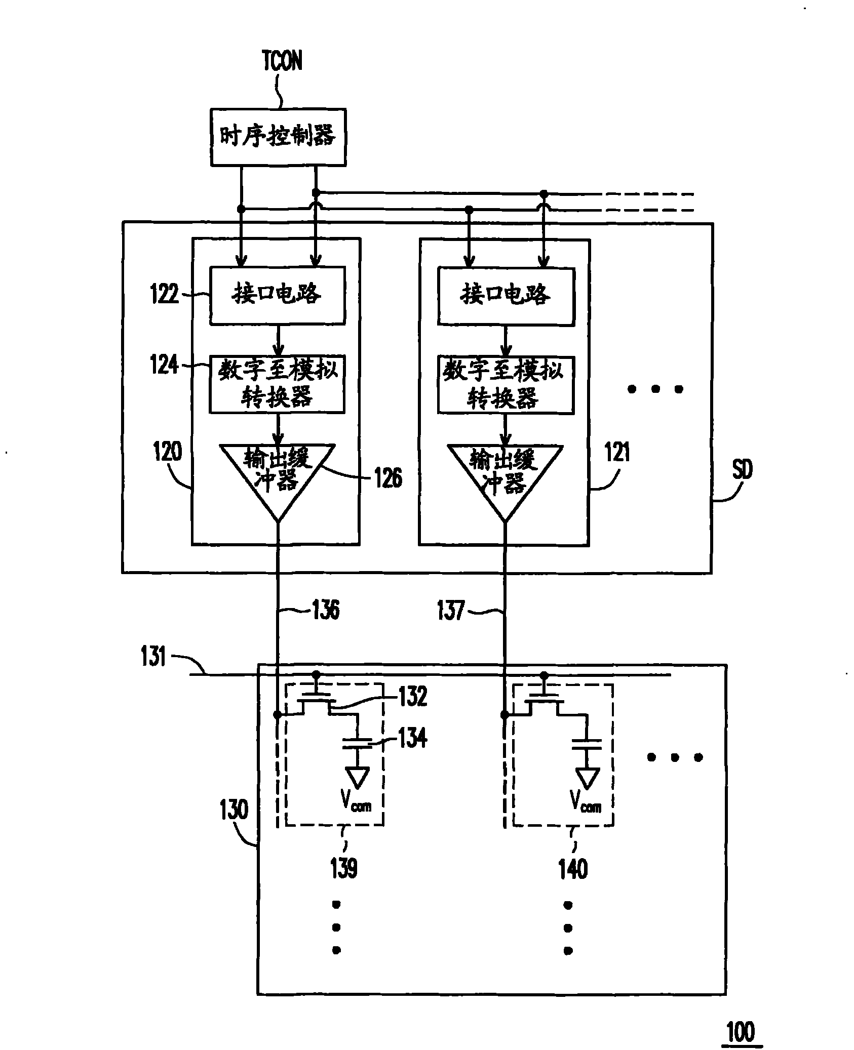
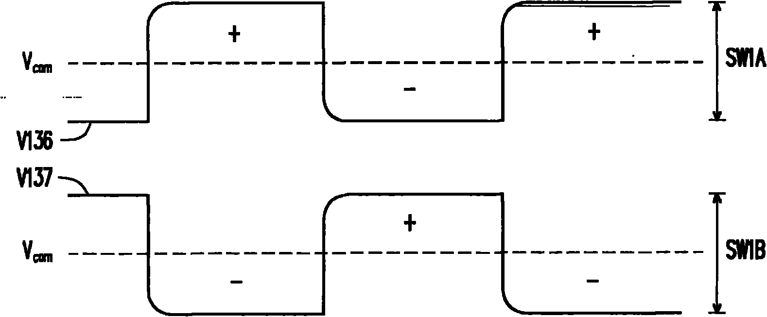
technical field [0001] The present invention relates to a source driver, and more particularly to a source driver for controlling its charge sharing function. Background technique [0002] Flat panel display devices, such as thin film transistor-liquid crystal displays (TFT-LCDs), are intended to replace conventional cathode ray tube (CRT) display devices. Compared with conventional CRT displays, TFT-LCD devices have advantages such as considerably lower operating voltage, lower power consumption, smaller and thinner, and lighter in weight. [0003] Figure 1A A conventional liquid crystal display 100 is shown. The liquid crystal display 100 includes a timing controller TCON, a source driver SD and a display panel 130 . Wherein, the source driver SD includes a plurality of source driving units 120 and 121 . Each source driving unit (for example, the source driving unit 120 ) includes an interface circuit 122 , a digital-to-analog converter (DAC) 124 and an output buffer 1...

Claims


Application Information

Patent Timeline
IPC IPC(8): G09G3/20G09G3/36
Inventor 翁孟泽陈英烈陈建儒李权哲
Owner HIMAX TECH LTD
Learn More