Smart grid-oriented power quality monitoring system and method
A power quality monitoring and smart grid technology, applied in the measurement of electrical variables, signal transmission systems, measurement of electricity and other directions, can solve problems such as insufficient high-speed, high-performance real-time data transmission and processing capabilities, improve the analog-to-digital conversion rate, and facilitate upgrades and expansions , the effect of meeting the monitoring needs
- Summary
- Abstract
- Description
- Claims
- Application Information
AI Technical Summary
Problems solved by technology
Method used
Image
Examples
Embodiment 1
[0044] This embodiment specifically describes a smart grid-oriented power quality monitoring system proposed by the present invention.
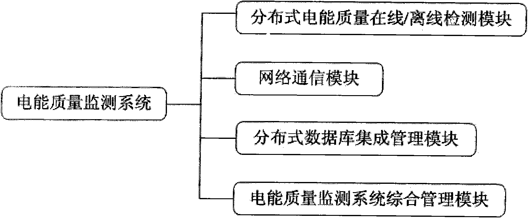
[0045] Such as figure 1 As shown, the system includes a distributed power quality online / offline node detection module, a network communication module, a distributed database integrated management module, and a power quality monitoring system integrated management module;
[0046] In terms of hardware design, the distributed power quality online / offline node monitoring module not only meets the basic performance index requirements for the measurement of complex power quality signals, but also considers the safety, reliability and low failure requirements of the detection device. The devices will not affect each other and can work together. This module is used to realize the basic distributed measurement function of the smart grid at the bottom of the power signal.
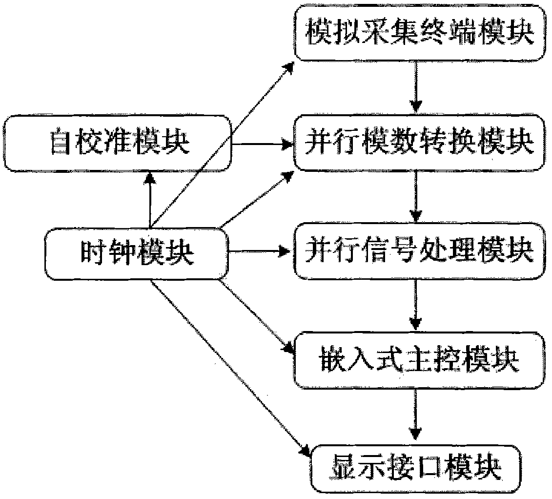
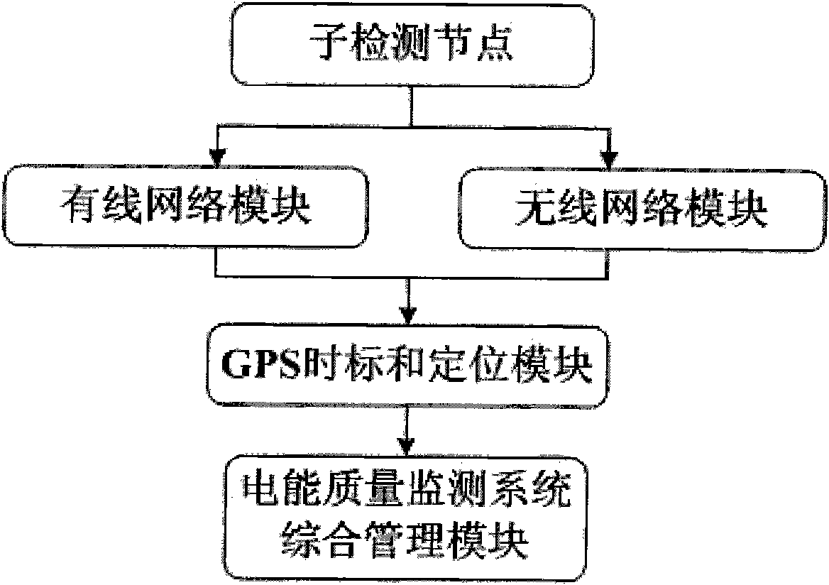
[0047] Such as figure 2 As shown, the distributed power quality online / off...
Embodiment 2
[0066] This embodiment specifically describes a smart grid-oriented power quality monitoring method proposed by the present invention.
[0067] Such as Figure 5 As shown, the method includes the following steps:
[0068] Step 1: Initialize the distributed power quality monitoring system;
[0069] Configure the basic functions of each node of the distributed power quality monitoring system through the main control management module, such as continuous tracking and monitoring of indicators such as voltage deviation, frequency deviation, harmonics, voltage fluctuations and flicker, and three-phase unbalance; and then The configuration command is sent to each monitoring node through the distributed communication network; after receiving the configuration command, each monitoring node starts the corresponding self-calibration program, and enters the corresponding monitoring state according to the monitoring mode described in the command after the self-calibration is successful. ...
Embodiment 3
[0083] Such as Figure 6 As shown, this embodiment specifically describes the parallel analog-to-digital conversion in the technical solution proposed by the present invention. Through the analog acquisition terminal module, the actual power signal is converted into a standard electrical input interface, and divided into four channels for the analog-to-digital conversion chip, and the analog-to-digital conversion chip is driven by the clock distribution module and the clock module to collect the incoming input in turn The signal is then transmitted to the parallel processing module through the programmable logic interface for power quality signal processing and data compression; through self-calibration, the accuracy of the analog acquisition terminal module is calibrated to realize the self-calibration function of the detection terminal module.
[0084] The clock distribution module divides a clock cycle evenly into 4 phases: 0-90 degrees, 90-180 degrees, 180-270 degrees, 270...
PUM
 Abstract
Description
Claims
Application Information
 - R&D
- Intellectual Property
- Life Sciences
- Materials
- Tech Scout
- Unparalleled Data Quality
- Higher Quality Content
- 60% Fewer Hallucinations
Browse by: Latest US Patents, China's latest patents, Technical Efficacy Thesaurus, Application Domain, Technology Topic, Popular Technical Reports.
© 2025 PatSnap. All rights reserved.Legal|Privacy policy|Modern Slavery Act Transparency Statement|Sitemap|About US| Contact US: help@patsnap.com


