Fuel supply device
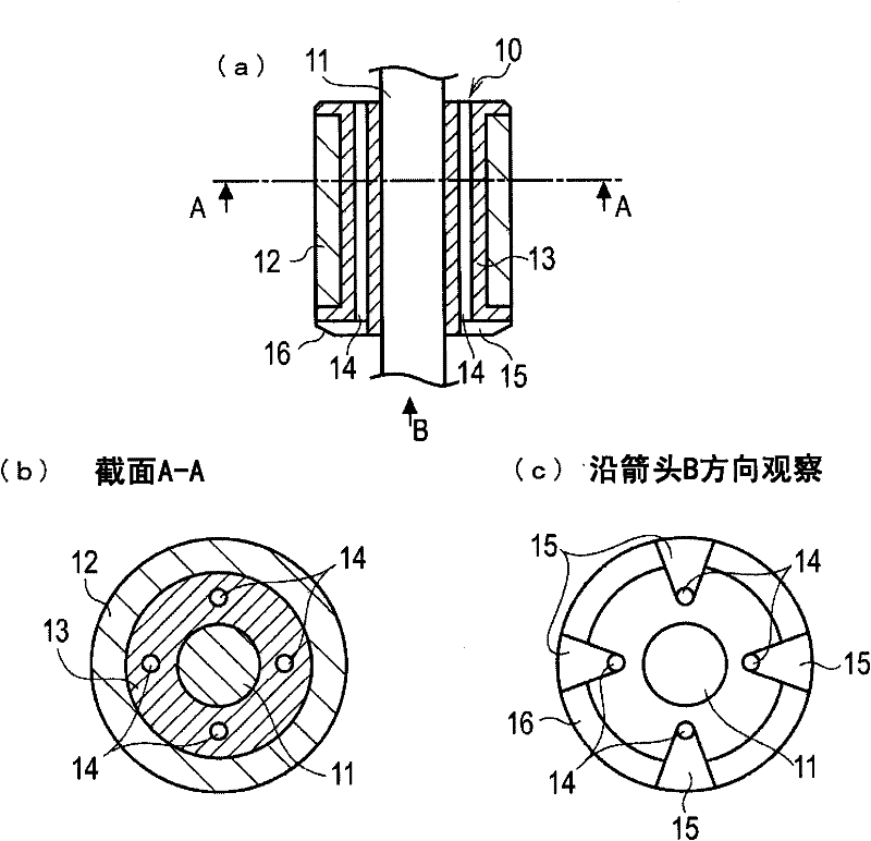
A fuel supply device and fuel technology, which is applied to liquid fuel feeders, electromechanical devices, charging systems, etc., can solve the problems of increasing the rigor of precision management of parts, increasing processing costs, abnormal noise, etc., to prevent wear and tear and Effects of overheating, improved stability, and reduced sliding loss
- Summary
- Abstract
- Description
- Claims
- Application Information
AI Technical Summary
Problems solved by technology
Method used
Image
Examples
Embodiment approach 1
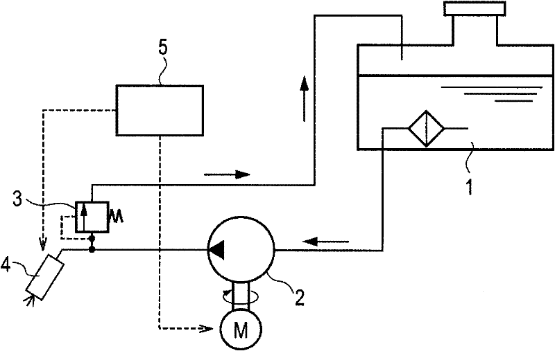
[0021] figure 1 It is a block diagram of the fuel system used for the fuel supply apparatus of this invention. The fuel supply device 2 is driven by a drive signal from the control unit 5, and the fuel supply device 2 sucks fuel from the fuel tank 1 through a filter and discharges it. The discharged fuel is adjusted to a predetermined pressure by the pressure regulator 3 and supplied to the fuel injection device 4 via a high-pressure fuel pipe. The fuel injection device 4 controls the injection timing and injection amount according to the engine speed and load, etc., to inject fuel into the intake pipe by means of a drive signal from the control unit 5 .
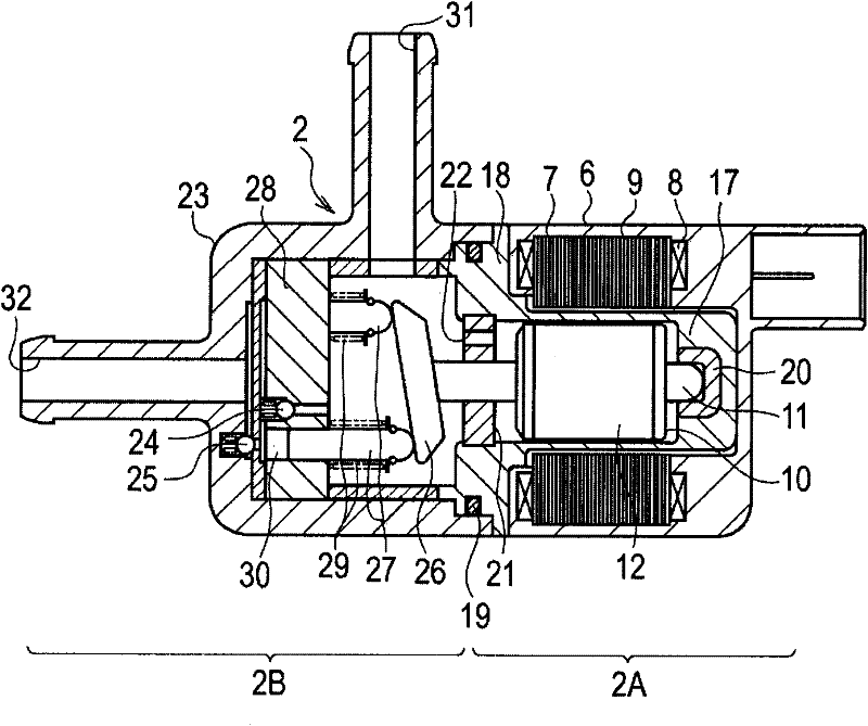
[0022] figure 2 It is a cross-sectional view showing the structure of the fuel supply device 2, and the fuel supply device 2 is composed of a motor unit 2A and a pump unit 2B. The motor unit 2A has a stator 9 composed of a stator core 7 arranged along the inner periphery of the bracket 6 and a plurality of stator coils 8...
Embodiment approach 2
[0036] The fuel supply device according to the second embodiment defines the positional relationship between the position of the fuel passage 14 provided in the rotor 10 and the plate 26 attached to the shaft 11 , and the other configurations are the same as those of the first embodiment.
[0037] Figure 5 (a) is a plan view of the end of the rotor 10, Figure 5 (b) is viewed from the direction of the arrow Figure 5 (a) Cross-sectional view of the D-D line cross-section. Such as Figure 5 As shown, in the structure of the second embodiment, the fuel passage 14 and the guide groove 15 are arranged symmetrically with respect to the line 35 connecting the upper dead center 33 and the lower dead center 34 of the plate 26 inclined on the shaft 11 and at equal intervals. According to this arrangement, by providing the fuel passage 14 and the guide groove 15, there is an effect that the motor does not vibrate when it rotates.
Embodiment approach 3
[0039] The fuel supply device according to the third embodiment is characterized by the formation position of the fuel passage 14 , and the other structures are the same as those of the first embodiment.
[0040] Figure 6 (a) is a sectional view of the rotor 10, Figure 6 (b) is viewed from the direction of the arrow Figure 6 (a) The sectional view of the section of line C-C, Figure 6 (c) is viewed from the direction of arrow D Figure 6 (a) Front view. Such as Figure 6 As shown, in the structure of the third embodiment, the fuel passage 14 is formed on the inner peripheral surface of the annular magnet 12 . The non-magnetic support body 13 is formed in a bobbin shape similarly to the first embodiment, and a guide groove 15 communicating with the fuel passage 14 is formed on one end surface thereof. In addition, the inclined surface 16 is also formed in the same manner as in the first embodiment.
[0041] In the case where the rotor 10 is formed by using the magnet ...
PUM
 Abstract
Description
Claims
Application Information
 - R&D
- Intellectual Property
- Life Sciences
- Materials
- Tech Scout
- Unparalleled Data Quality
- Higher Quality Content
- 60% Fewer Hallucinations
Browse by: Latest US Patents, China's latest patents, Technical Efficacy Thesaurus, Application Domain, Technology Topic, Popular Technical Reports.
© 2025 PatSnap. All rights reserved.Legal|Privacy policy|Modern Slavery Act Transparency Statement|Sitemap|About US| Contact US: help@patsnap.com


