Method for controlling an electric disconnecting switch motor

An electrical isolation and motor technology, applied in electrical switches, power devices inside switches, circuits, etc., can solve the problems of accidental operation of isolation switches, increased current, and high rated voltage.

Inactive Publication Date: 2011-05-04
多菲内电机构造公司
View PDF4 Cites 0 Cited by
  • Summary
  • Abstract
  • Description
  • Claims
  • Application Information

AI Technical Summary

Problems solved by technology

[0011] In most cases, this voltage is higher than the rated voltage of the motor, thus causing an increase in current, which exceeds the threshold used to trigger the protective device
However, in the specific case where the rated voltage of the motor corresponds to the mains voltage, rectified if available, this thermal cutout is not triggered and the motor is then powered, thus leading to unintentional operation of the isolating switch

Method used


Image

  • Method for controlling an electric disconnecting switch motor
  • Method for controlling an electric disconnecting switch motor

Examples


Embodiment Construction

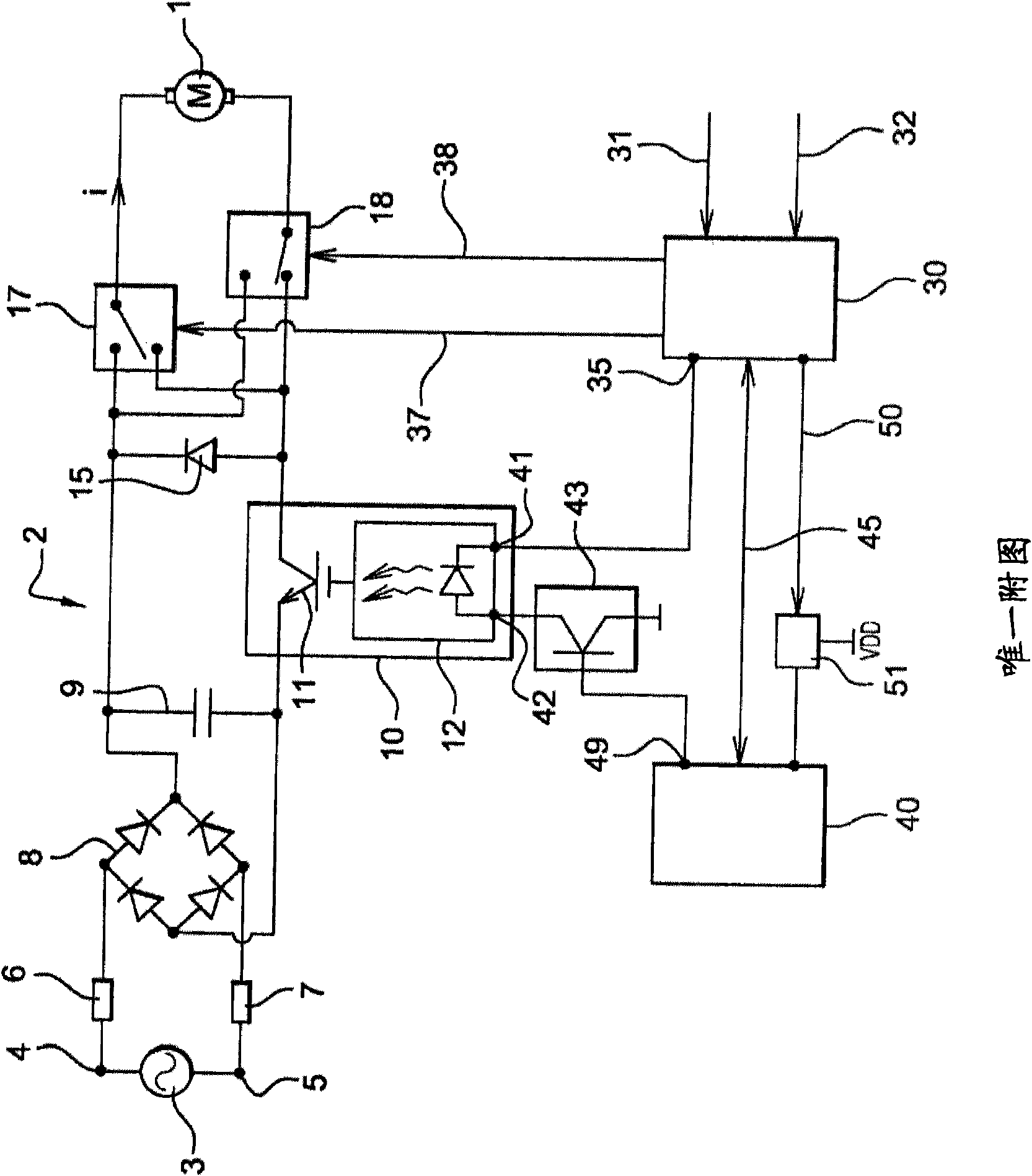
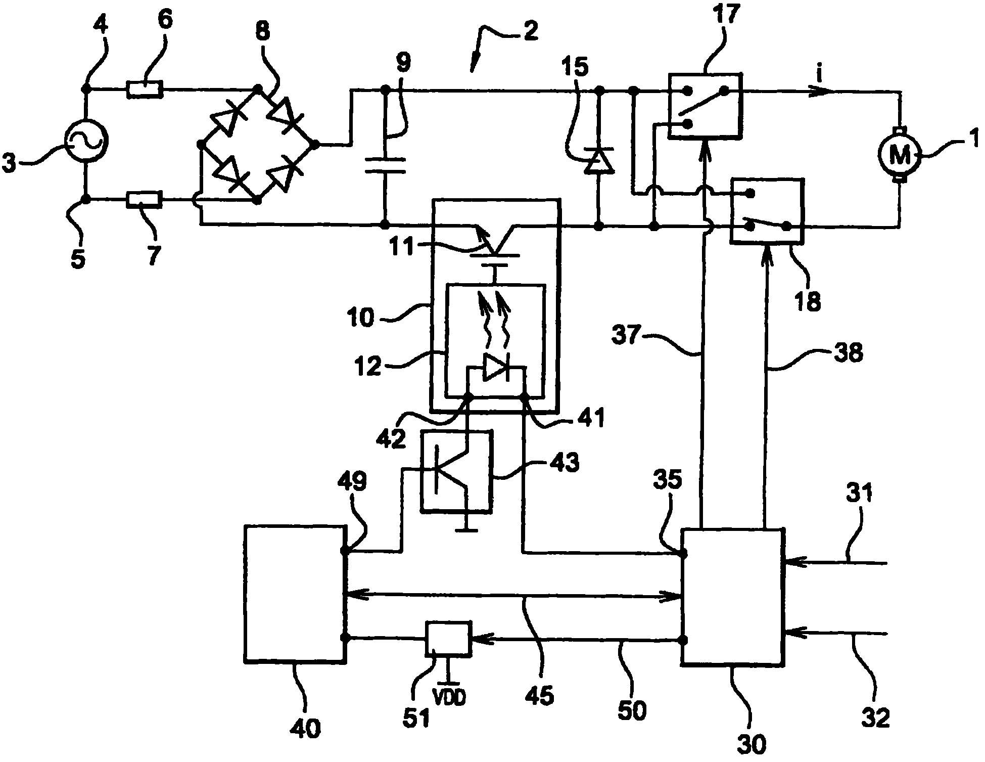
[0029] As shown in Figure 1, the motor (1) of the disconnector is powered by a circuit (2), which is connected to a mains voltage source (3), which in this example is shown as AC power source. Via connections (4, 5) to the AC circuit, the circuit (2) thus comprises a set of fuses (6, 7) connected to a rectifier (8) in the form of a diode bridge, said rectifier (8) being connected between capacitors (9 ) to output a substantially constant voltage.

[0030] Downstream of the capacitor (9) there is a voltage chopper arrangement comprising a power converter (10) comprising for example an IGBT ( Insulated Gate Bipolar Transistor) type static switch (11).

[0031] Downstream of the freewheeling diode (15) there are two relays (17, 18) which are part of the circuit for supplying electrical energy to the motor (1). The direction of current flow in the motor is set according to the position of the contacts of the relays (17, 18).

[0032] In the illustrated embodiment corresponding...


PUM


Abstract

The invention relates to a device for controlling an electric disconnecting switch motor (1), including: a power supply circuit (2) for supplying power to the motor (1) from a network voltage source (3), said circuit including a static converter (10) controlled to output a voltage having a predetermined value to the motor (1); and one or more configuration components, the actuation of which enables the configuration (17, 18) of said circuit with a view to setting the direction of the current (1) that flows in the motor (1), characterized in that the controls of the static converter (10) and the controls of the configuration component (17, 18) are provided by two separate control units (30, 40), each outputting control instructions, the control instructions of one of the two control units being activated on the basis of a validation instruction from the other control unit.

Description

technical field [0001] The invention relates to a device for electrically controlling the operation of an electrical disconnector. More specifically, the invention relates to a method of designing or adjusting various operations related to the operation, namely, of powering an electric motor and determining the direction of rotation of this same motor. Background technique [0002] Generally speaking, to control the opening and closing of the disconnector, an electric motor is used, which utilizes a gear reducer to make a moving part for the disconnector. When the motor is driven long enough, the motor can thus ensure that the moving parts of the disconnector are displaced in order to open or close the disconnector. [0003] More precisely, the direction of movement of the moving part of the disconnector is set by configuring the power supply circuit of the motor. A suitable set of relays can reverse the direction of connection of the motor's coils relative to the voltage ...

Claims


Application Information

Patent Timeline
Patent Type & Authority Applications(China)
IPC IPC(8): H01H3/26
CPCH01H3/26H01H2003/266
Inventor 弗兰克·吉略诺伯特·罗赞德
Owner 多菲内电机构造公司
Why Eureka
Try Eureka