A material testing machine

A material testing machine and material testing technology, applied in the direction of analyzing materials, instruments, measuring devices, etc., can solve the problems of test piece damage, splashing, etc., and achieve the effect of simple structure

Active Publication Date: 2015-02-11
SHIMADZU SEISAKUSHO CO LTD
View PDF8 Cites 0 Cited by
  • Summary
  • Abstract
  • Description
  • Claims
  • Application Information

AI Technical Summary

Problems solved by technology

In addition, when performing a compression test in which a compressive force is applied to the test piece, the test piece may be damaged and a part of it may be splashed.

Method used


Image

  • A material testing machine
  • A material testing machine
  • A material testing machine

Examples


Embodiment Construction

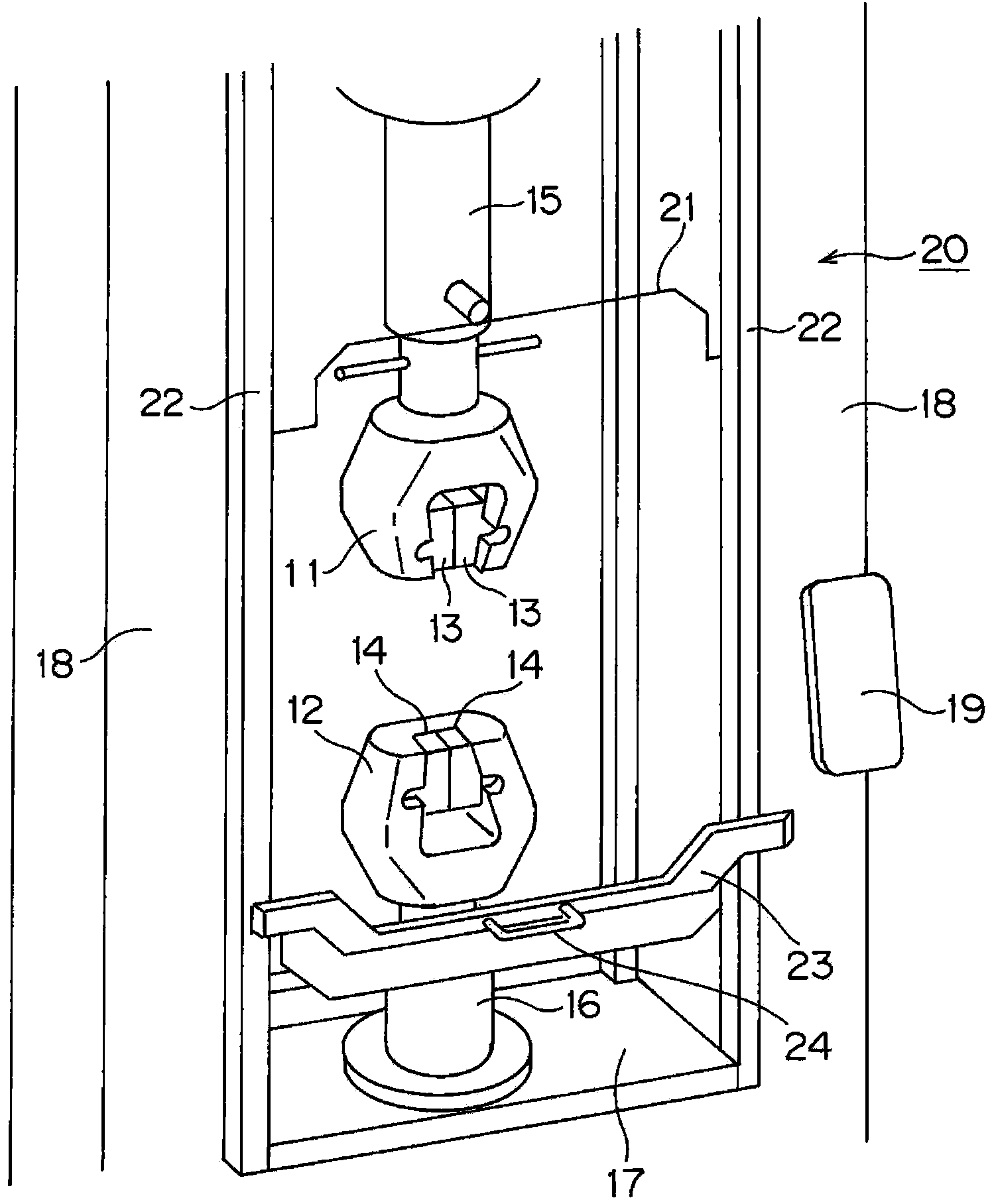
[0030] Embodiments of the present invention will be described below based on the drawings. figure 1 A perspective view showing key parts of the material testing machine involved in the present invention.

[0031] This material testing machine has a pair of columns 18 erected on a table 17 , and a crosshead (not shown) that moves up and down along the columns 18 by driving a screw disposed inside the columns 18 . An upper jig 11 having a pair of gripping teeth 13 for gripping the upper end of the test piece is disposed on the crosshead through a coupling 15 . On the other hand, a lower jig 12 having a pair of gripping teeth 14 for gripping the lower end of the test piece is disposed on the table via a coupling 16 .

[0032] In this material testing machine, when performing a tensile test on a test piece, the input unit 19 inputs necessary test conditions and the like. Then, in a state where both ends of the test piece are held by the upper jig 11 and the lower jig 12 , the cr...


PUM


Abstract

The objective of the invention is to provide a material testing machine capable of configuring a sputtering prevention shade to the optimum position corresponding to the form of a material test. The material testing machine is provided with: a position detection and limitation component (40) and an abutting component (30), wherein the position detection and limitation component (40) is provided with a microswitch (42) used for determining whether the sputtering prevention shade exits or not, and a limitation part (41) used for limiting the position of the sputtering prevention shade (21); the position detection and limitation component (40) can be installed on a plurality of positions at an interval of a first distance on a frame (22); and the abutting component (30) can be separately abutted to the microswitch (42) and the limitation part (41), and can be installed on a plurality of positions at an intervals of a second distance on the sputtering prevention shade (21).

Description

technical field [0001] The present invention relates to a material testing machine provided with a splash prevention cover capable of corresponding to the height position of a test piece during a material test and movable in one direction. Background technique [0002] This material testing machine has: a pair of pillars erected on a workbench, screws arranged inside these pillars, and a crosshead that is raised and lowered along the pillars by synchronous rotation of these screws. An upper fixture for holding the upper end of the test piece is arranged on the crosshead, and a lower fixture for holding the lower end of the test piece is arranged on the table. When carrying out the tensile test on the test piece, the crosshead is raised with respect to the base while the both ends of the test piece are held by the upper jig and the lower jig, and a tensile load is applied to the test piece. [0003] When using this material testing machine to perform a tensile test on a test...

Claims


Application Information

Patent Timeline
Patent Type & Authority Applications(China)
IPC IPC(8): G01N3/02
Inventor 小岭德晃
Owner SHIMADZU SEISAKUSHO CO LTD
Why Eureka
Try Eureka