Padlock device and transfer switch appliance using it

A lock device and conversion mechanism technology, applied in the direction of electric switches, circuits, electrical components, etc., can solve the problems of poor safety and achieve the effect of ensuring safety

Active Publication Date: 2019-09-20
SCHNEIDER WINGOAL TIANJIN ELECTRIC EQUIP
View PDF17 Cites 0 Cited by
  • Summary
  • Abstract
  • Description
  • Claims
  • Application Information

AI Technical Summary

Problems solved by technology

[0005] The purpose of the present invention is to provide a padlock device and a changeover switch device using it, so as to improve the technical problem of poor security of the existing padlock device

Method used


Image

  • Padlock device and transfer switch appliance using it
  • Padlock device and transfer switch appliance using it
  • Padlock device and transfer switch appliance using it

Examples


Embodiment Construction

[0028] The present invention will be further described below in conjunction with the accompanying drawings and specific embodiments, but the following embodiments in no way limit the present invention.

[0029] In the description of the present invention, it should be noted that unless otherwise specified and limited, the terms "connection" and "communication" should be understood in a broad sense, for example, it can be a fixed connection, a detachable connection, or an integral Ground connection; it can be a mechanical connection, a signal connection, or an electrical connection; it can be a direct connection, or an indirect connection through an intermediary, or an internal connection between two components. Those of ordinary skill in the art can understand the specific meanings of the above terms in the present invention in specific situations. Furthermore, the terms "first", "second", "third", "fourth", and "fifth" are used for descriptive purposes only and should not be ...


PUM


Abstract

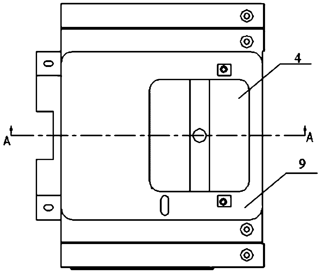
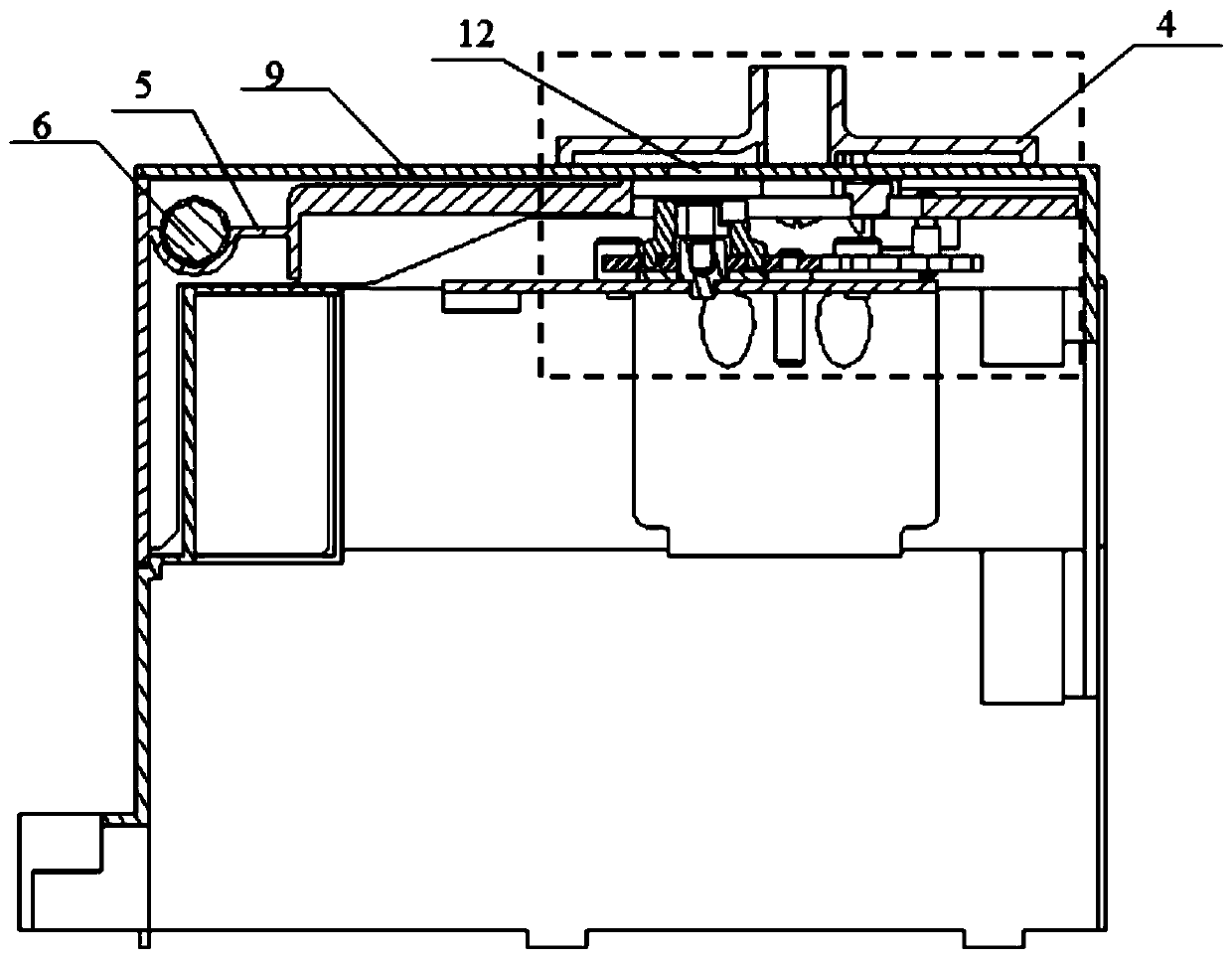
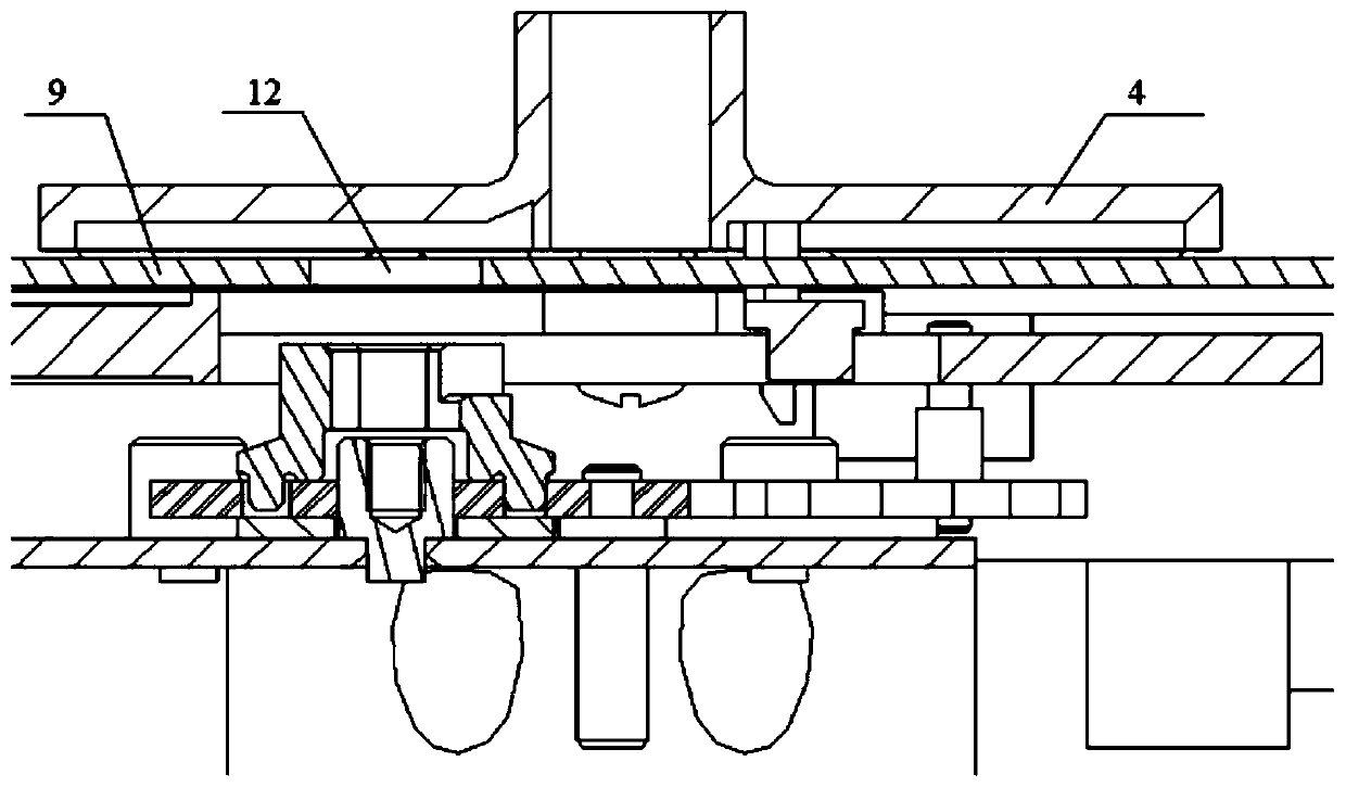
The invention discloses a locking device and transfer switching equipment using the same, and relates to the technical field of low-voltage apparatus, so as to improve the technical problem of fairlylow safety of existing locking device. The invention provides a locking device which comprises a hand-operated switching mechanism and a shell mechanism, wherein the hand-operated switching mechanismcomprises a main gear, a first switching gear and a second switching gear; the main gear is configured to drive the first switching gear or the second switching gear to rotate; a first interlocking column is arranged on the first switching gear and cooperates with the first switching gear to realize an interlocking effect when a main power supply is switched on; a second interlocking column is arranged on the second switching gear and cooperates with the second switching gear to realize an interlocking effect when a backup power supply is switched on; the shell mechanism comprises a slip coverand a handle box connected with the slip cover; a handle is arranged in the handle box; and after being taken out, the handle is used for driving the main gear to rotate.

Description

technical field [0001] The invention relates to the technical field of low-voltage electrical appliances, in particular to a padlock device and a transfer switch appliance using the same. Background technique [0002] Due to the process or use requirements, the equipment cannot be powered off during operation, and a transfer switch is required at this time. A transfer switch is an electrical appliance used to switch one or several load circuits from one power source to another when the power supply is interrupted, thereby ensuring continuous power supply. [0003] The transfer switch usually has three execution states: main power closing, backup power closing and double opening. In the double-point state, the transfer switch cuts off the two power supplies of the main power supply and the backup power supply at the same time to achieve the effect of disconnecting the power supply, so as to ensure that there will be no electric operation when the maintenance personnel manual...

Claims


Application Information

Patent Timeline
Patent Type & Authority Patents(China)
IPC IPC(8): H01H9/28
Inventor 郭小龙陈红群薄同伟王权张晓佟王义恒石少强
Owner SCHNEIDER WINGOAL TIANJIN ELECTRIC EQUIP
Why Eureka
Try Eureka