Mechanical interlocking device for power supply of load switch cabinet with dual power supply for ring network cabinet

A dual power supply, load switch cabinet technology, applied in the direction of electrical switches, circuits, electrical components, etc., can solve problems such as false opening, failure to achieve mechanical interlocking, and incorrect closing of load switch cabinets, and achieve power supply guarantees. Effect

Active Publication Date: 2017-08-29
上海安奕极企业发展股份有限公司
View PDF5 Cites 0 Cited by
  • Summary
  • Abstract
  • Description
  • Claims
  • Application Information

AI Technical Summary

Problems solved by technology

[0003] The interlocking function of the original dual power supply load switch cabinet of the ring network cabinet is not perfect: 1. When one load switch cabinet is powered, it is easy to cause the other load switch cabinet to be closed or opened by mistake due to no interlocking ; 2. When the power supply of a load switch cabinet encounters a failure, it is necessary to manually open the switch cabinet before closing the other load switch cabinet for power supply.
Since there is no interlock function between the two load switch cabinets, the power supply cannot be reliably guaranteed, and there are hidden dangers to the safety of operators and maintenance personnel.
According to the current national strategic goal of building a strong smart grid and the requirements for the construction of smart high-voltage switchgear, the original mechanism cannot play a role in mechanical interlocking, and cannot provide a reliable guarantee for the realization of smart switchgear.

Method used


Image

  • Mechanical interlocking device for power supply of load switch cabinet with dual power supply for ring network cabinet
  • Mechanical interlocking device for power supply of load switch cabinet with dual power supply for ring network cabinet
  • Mechanical interlocking device for power supply of load switch cabinet with dual power supply for ring network cabinet

Examples


Embodiment Construction

[0019] In order to make the technical means, creative features, goals and effects achieved by the present invention easy to understand, the present invention will be further described below in conjunction with specific illustrations.

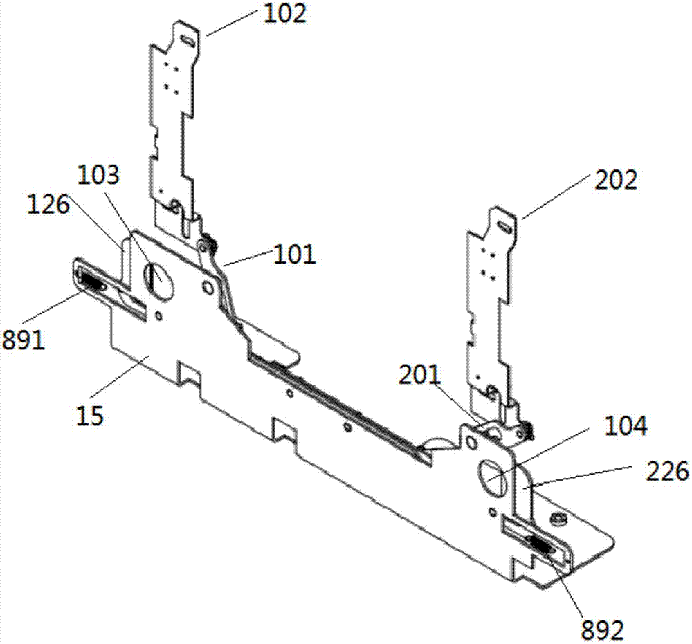
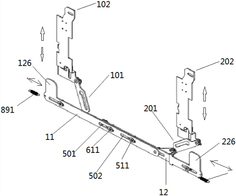
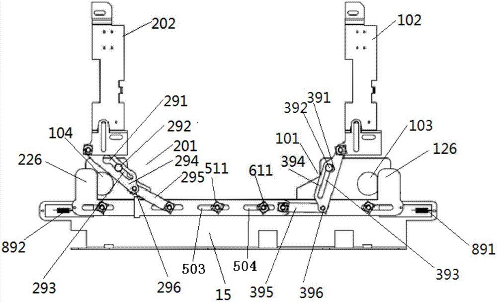
[0020] see figure 1 , figure 2 , the mechanical interlocking device of the present invention for the power supply of the load switch cabinet with dual power supply for the ring network cabinet is used for the load switch cabinet with dual power supply for the ring network cabinet, and has two power switch structures. Among them, the power indicator board 102 is connected with the structure of the load switch cabinet on the left, and the power indicator board 202 is connected with the structure of the load switch cabinet on the right. The action of the power switch of each load switch cabinet will cause the corresponding power indicator board 102, 202 up and down movement.

[0021] The mechanical interlocking device of the present invention fo...


PUM


Abstract

The invention discloses a machinery interlocking device used for a ring network cabinet dual-power-supply load cabinet power supply, comprising two sliding plates which can slide horizontally, and two pull rod mechanisms; one end of each pull rod mechanism is connected to one end of the sliding plate; the other end of the pull rod mechanism is in rotation connection with the power supply indication board of a corresponding switch cabinet; the other end of the sliding plate is provided with a baffle corresponding to the operation position of the switch of the switch cabinet ; and the baffle can block the operation of the switch of the switch cabinet. The machinery interlocking device used for the power supply of the ring network cabinet dual-power-supply load cabinet comprises two sliding plates which can slide horizontally and two pull rod mechanisms, the one end of each pull rod mechanism is in rotation connection with one end of the sliding plate, and the other end is in rotation connection with the indication board of the power supply. As a result, the operation hole of the load switch cabinet is plugged while the other load switch cabinet is switched off, so that the load switch cabinet is not mistakenly closed, which acts as an interlocking function and enables the power supply of the dual power supply switch cabinet to be guaranteed.

Description

technical field [0001] The invention relates to the technical field of a medium-voltage ring network cabinet, in particular to a mechanical interlock device for power supply of a dual-power load switch cabinet. Background technique [0002] With the wide application of the ring network cabinet in the power system, people have put forward new technical requirements for the technology of the ring network cabinet industry, mainly for the higher and higher power supply requirements in the power supply system, and the dual power supply is especially important. [0003] The interlocking function of the original dual power supply load switch cabinet of the ring network cabinet is not perfect: 1. When one load switch cabinet is powered, it is easy to cause the other load switch cabinet to be closed or opened by mistake due to no interlocking 2. When a load switch cabinet power supply runs into a fault, it is necessary to manually open the switch cabinet before another load switch ca...

Claims


Application Information

Patent Timeline
Patent Type & Authority Patents(China)
IPC IPC(8): H01H9/26
CPCH01H9/26
Inventor 李烽沈华伦周益刚王召洋李亚国
Owner 上海安奕极企业发展股份有限公司
Why Eureka
Try Eureka