
Automatic detergent feeding system

A technology of automatic dosing and detergent, applied in washing devices, other washing machines, textiles and papermaking, etc., can solve the problems of high cost and complex structure, and achieve the effects of improving efficiency, simple structure and reducing pollution

Active Publication Date: 2011-05-04
QINGDAO HAIER WASHING MASCH CO LTD
View PDF8 Cites 42 Cited by
  • Summary
  • Abstract
  • Description
  • Claims
  • Application Information

AI Technical Summary

Problems solved by technology

Although this structure can realize precise control of detergent, the structure is complicated and the cost is high

Method used


Image

  • Automatic detergent feeding system
  • Automatic detergent feeding system
  • Automatic detergent feeding system

Examples


Embodiment 1

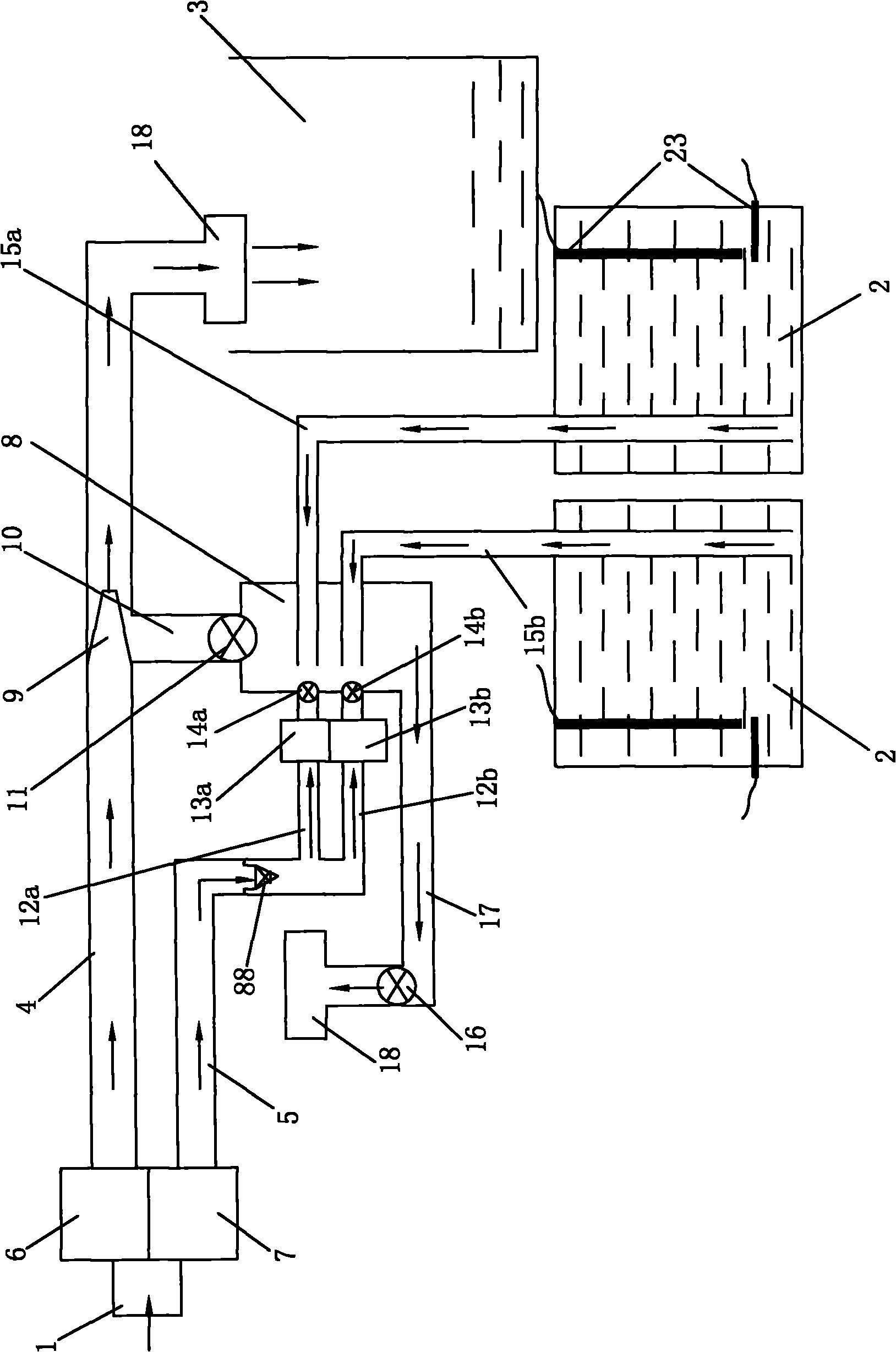
[0032] like figure 1 As shown, the cleaning control valve includes an electromagnet that generates a driving source and a rubber-wrapped magnet ball valve. The cleaning water path between the cleaning water valve 7 and the constant volume container 8 is provided with two shunts 12a corresponding to the two detergent containers. , 12b, the shunts 12a, 12b are respectively provided with electromagnets 13a, 13b, after the electromagnets 13a, 13b are energized, they can attract the magnet ball valves 14a, 14b to close the shunts 12a, 12b and open the constant volume container 8 and the detergent container 2 The passage 15a, 15b between, or the water inlet shock magnet ball valve 14a, 14b opens the shunt 12a, 12b between the cleaning water valve 7 and the constant volume container 8 and closes the passage between the constant volume container 8 and the detergent container 2 15a, 15b.

[0033] The one-way valve described in this embodiment is one, and is arranged on the main road o...

Embodiment 2

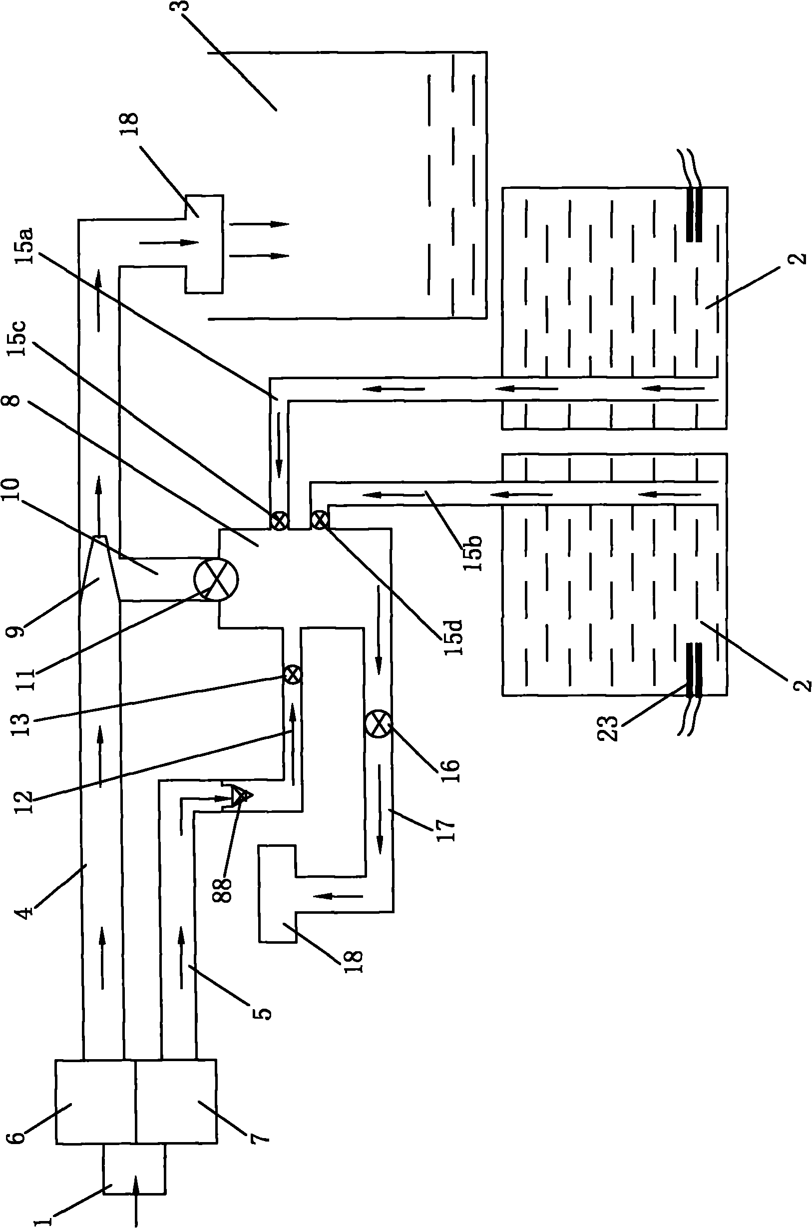
[0035] like figure 2 As shown, the cleaning control valve and the detergent control valve are all solenoid valves, the constant volume container 8 is connected with the detergent container 2 containing the washing liquid and softener respectively, and the passages 15a, 15b are connected to the constant volume container 8 Solenoid valves 15c and 15d are respectively arranged at each place. There is only one passage 12 between the cleaning water valve 7 and the constant volume container 8, and a solenoid valve 13 is also provided at the connection between the passage 12 and the constant volume container 8.

Embodiment 3

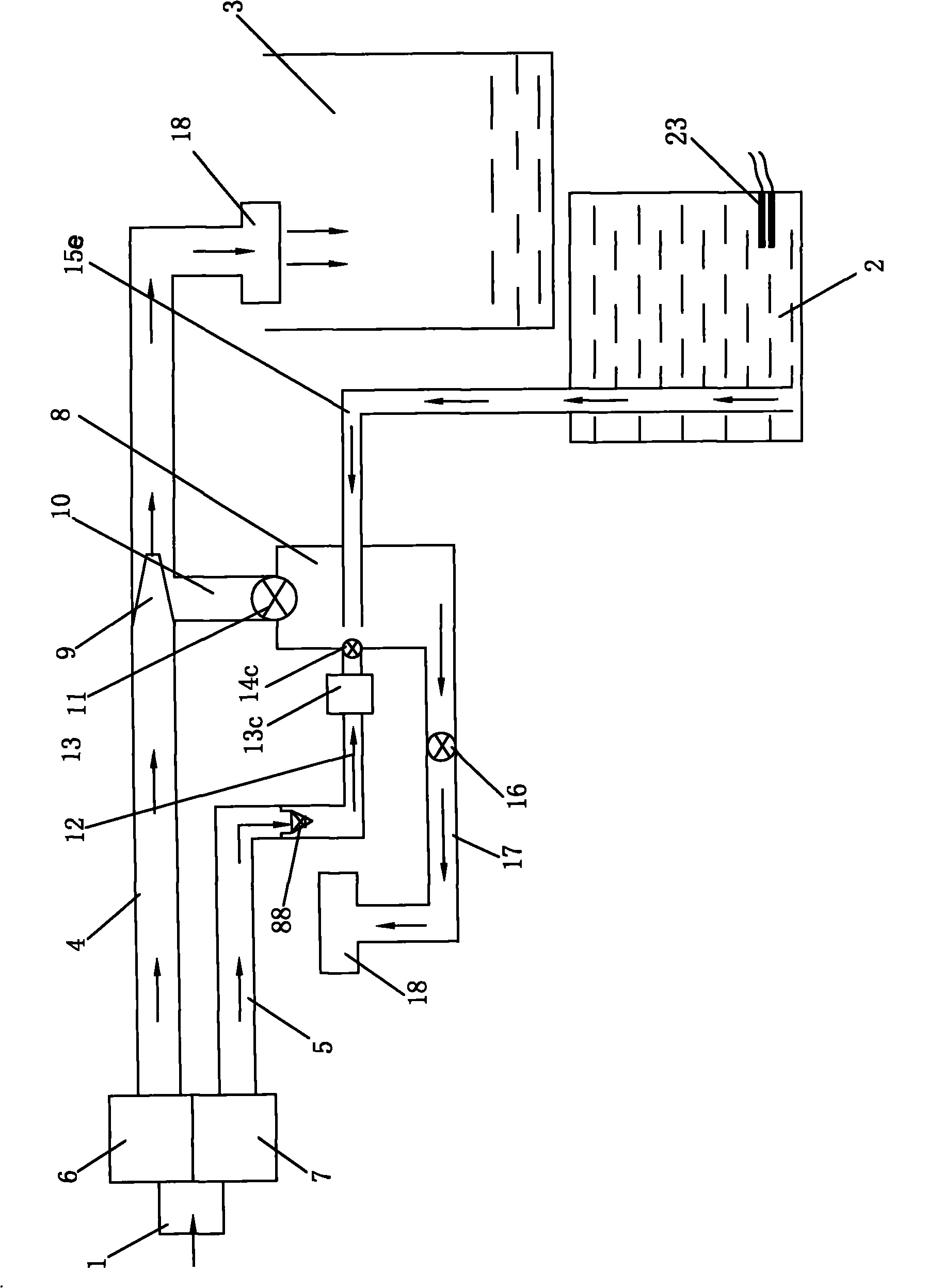
[0037] like image 3 As shown, this embodiment is different from Embodiments 1 and 2. There is only one passage 12 between the cleaning water valve 7 and the constant volume container 8, and there is only one detergent container. The passage 15e is between the detergent container and the constant volume container. The passage 12 is provided with an electromagnet 13c. After the electromagnet 13c is energized, it can attract the magnet ball valve 14c to close the passage 12 and open the passage 15e between the constant volume container 8 and the detergent container 2, or the incoming water impacts the magnet ball valve 14c to open the cleaning water. The passage 12 between the valve 7 and the constant volume container 8 closes the passage 15 e between the constant volume container 8 and the detergent container 2 .

[0038] The one-way valve described in the second and third embodiments above is one, and is arranged between the cleaning water valve and the cleaning control valve ...


PUM


Abstract

The invention discloses an automatic detergent feeding system, which is arranged between a washing drum and a water inlet of a washing machine. The automatic feeding system comprises a main water inlet passage, a cleaning water passage, a detergent container and a constant volume container, wherein the main water inlet passage is provided with a venturi pipe capable of generating negative pressure when water flows, the rear side of the outlet of the venturi pipe is provided with a bypass branch pipe for extracting the negative pressure, the bypass branch pipe is communicated with the constant volume container, the cleaning water passage and the detergent container are communicated with the constant volume container respectively, the constant volume container is communicated with the washing drum through a water outlet pipeline, and a one-way valve for preventing a detergent from reflowing to the water inlet is also arranged in the cleaning water passage; and a main water inlet valve is arranged between the main water inlet passage and the water inlet, a cleaning water valve is arranged between the cleaning water passage and the water inlet, a cleaning control valve is arranged at the connected position of the cleaning water passage and the constant volume container, a closing control valve for closing a connected port is arranged at the connected port of the constant volume container and the bypass branch pipe, and the water outlet pipeline is provided with a water outlet control valve. The automatic feeding system has simple structure and improves the clothes washing efficiency.

Description

technical field [0001] The invention relates to a detergent adding system of a washing machine, in particular to an automatic detergent feeding system. Background technique [0002] The detergent used in the washing process of the traditional washing machine is placed separately from the washing machine. There is no detergent adding device on the washing machine, and the detergent cannot be added automatically. This structure cannot realize the automatic washing control process of the washing machine. With the improvement of washing machine automation, most washing machines are set to connect the detergent box for placing detergent or / and softener with the water inlet pipeline, and flush the detergent or / and softener in the detergent box into the washing tub through the water inlet However, this structure must first put detergent or / and softener into the detergent box every time the laundry is done, and the automatic laundry control process has not been realized equally. ...

Claims


Application Information

Patent Timeline
Patent Type & Authority Applications(China)
IPC IPC(8): D06F39/02D06F39/08
Inventor 吕佩师许升鲍睿李维赞杨明旭
Owner QINGDAO HAIER WASHING MASCH CO LTD
Learn More