Eureka AIR delivers breakthrough ideas for toughest innovation challenges, trusted by R&D personnel around the world.

On-stream method of residual oil hydrogenation process

A technology for residual oil hydrogenation and process, which is applied in the directions of chemical instruments and methods, catalyst activation/preparation, physical/chemical process catalysts, etc., and can solve the problems of on-time start-up of residual oil hydrogenation units, increased production costs, and increased processing costs, etc. problems, to achieve the effect of reducing human body damage, reducing usage, and uniform pre-vulcanization process

Active Publication Date: 2011-05-04
CHINA PETROLEUM & CHEM CORP +1
View PDF9 Cites 19 Cited by
  • Summary
  • Abstract
  • Description
  • Claims
  • Application Information

AI Technical Summary

Problems solved by technology

When the residual oil hydrogenation catalyst is presulfided, generally all types of catalysts are vulcanized separately. Since there are many types of catalysts, each catalyst has different properties, and the required sulfidation treatment conditions are also slightly different. When the hydrogen catalyst is presulfurized, the production process is more complicated
At the same time, the amount of catalyst is large, and the amount of catalyst that requires external presulfidation treatment is relatively large. The external pretreatment process takes a long time, and the processing cost increases. Under the circumstances, it may affect the on-time start-up of the residual oil hydrogenation unit
At the same time, due to the low strength of certain types of catalysts, it is easy to cause excessive loss during the pre-sulfurization process outside the device, resulting in increased production costs.

Method used


Image

  • On-stream method of residual oil hydrogenation process

Examples


Embodiment 1

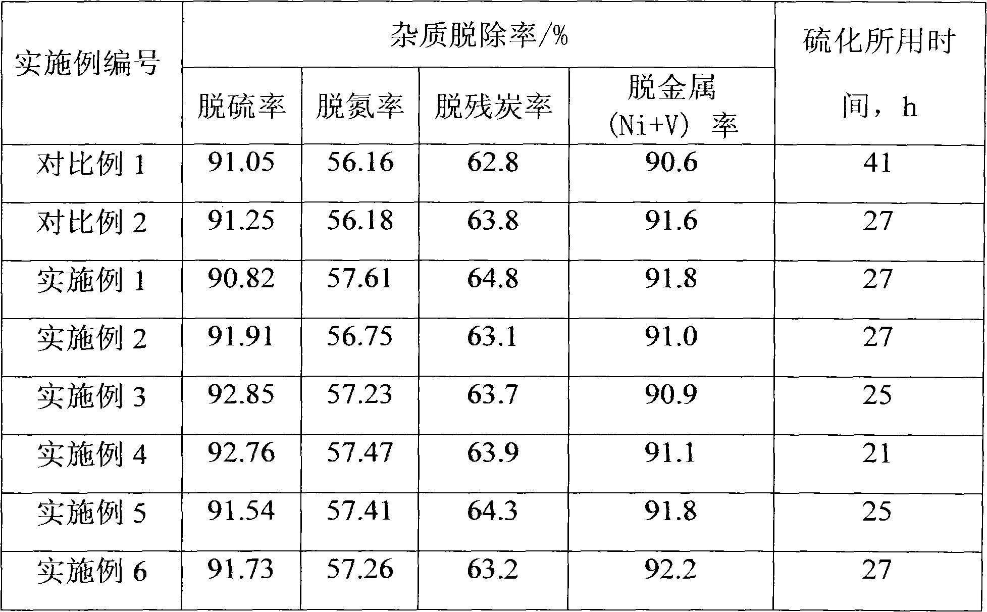
[0050] 50g of FZC-102 and 100g of FZC-30 are respectively immersed in 10g and 15g of organic solvent (organic solvent is coking kerosene fraction), the proportion of carbon atoms in the organic solvent is not less than 50%, and the immersion time is 1 hour. The vulcanizing agent used in the FZC-102 catalyst is 10g of elemental sulfur and 2.5g (NH 4 ) 2 S mixture, the vulcanizing agent that FC-30 catalyst uses is elemental sulfur 20g and 5g (NH 4 ) 2 S mixture. The impregnated FZC-102 and FZC-30 were mixed with corresponding vulcanizing agents respectively, and treated at 170°C for 3 hours, and cooled naturally. The obtained presulfurized catalyst, presulfurized FZC-102 catalyst and presulfurized FZC-30 catalyst, oxidized state FZC-20 and oxidized state FZC-40 catalyst are divided into small-sized reactors (contact FZC-102 earlier by reaction materials, Then contact with FZC-20 and contact with FZC-30, and finally contact with FZC-40 in the order of filling, other embodimen...

Embodiment 2

[0052] 50g of FZC-102 and 100g of FZC-40 are respectively immersed in 10g and 15g of organic solvent (organic solvent is coking kerosene fraction), the ratio of carbon number 9 to 12 in the organic solvent is not less than 50%, and the immersion time is 1 hour. The vulcanizing agent used in the FZC-102 catalyst is 10g of elemental sulfur and 2.5g (NH 4 ) 2 S mixture, the vulcanizing agent that FC-40 catalyst uses is the (NH 4 ) 2 S mixture. The impregnated FZC-102 and FZC-40 were mixed with corresponding vulcanizing agents respectively, and treated at 170°C for 3 hours, and cooled naturally. The obtained presulfided catalyst, presulfurized FZC-102 catalyst and presulfided FZC-40 catalyst, oxidized state FZC-20 and oxidized state FZC-30 catalyst are divided into small reactors according to the order of embodiment 1, and the airtightness is qualified. Start to raise the temperature at 20°C / h, rise to 220°C, and keep the temperature constant for 8 hours. End the constant tem...

Embodiment 3

[0054] 50g of FZC-102 and 100g of FZC-30 are respectively immersed in 15g and 20g of organic solvents (organic solvents are coking kerosene fractions), the proportion of carbon atoms 9-12 in the organic solvents is not less than 50%, and the immersion time is 1 hour. The vulcanizing agent that FZC-102 catalyst uses is elemental sulfur 15g and 3.5g (NH 4 ) 2 S mixture, the vulcanizing agent that FC-30 catalyst uses is elemental sulfur 15g and 4g (NH 4 ) 2 S mixture. The impregnated FZC-102 and FZC-30 were mixed with corresponding vulcanizing agents respectively, and treated at 170°C for 3 hours, and cooled naturally. The obtained presulfided catalyst, the presulfurized FZC-102 catalyst, the presulfided FZC-30 catalyst, the oxidized state FZC-20 and the oxidized state FZC-40 catalyst are divided into small reactors according to the order of Example 1, and the airtightness is qualified , start to raise the temperature at 20°C / h, rise to 220°C, and keep the temperature constan...


PUM

PropertyMeasurementUnit
diameteraaaaaaaaaa

Abstract

The invention discloses an on-stream method of a residual oil hydrogenation process, comprising the steps of: selecting oxidation-state residual oil hydrogenation serial catalysts according to the requirement of the residual oil hydrogenation process, wherein the oxidation-state residual oil hydrogenation serial catalysts comprise a residual-oil-hydrogenation protective agent, a residual-oil-hydrogenation demetalization catalyst, a residual-oil-hydrogenation desulfurization catalyst and a residual-oil-hydrogenation denitrification agent; treating the residual-oil-hydrogenation protective agent, the oxidation-state residual-oil-hydrogenation desulfurization catalyst and the oxidation-state residual-oil-hydrogenation denitrification agent by using an ex-situ pre-sulfurization method; and loading the needed catalysts in a reactor, heating, activating and switching the residual oil raw materials to carry out the hydrogenation. Through the method provided by the invention, ex-situ pre-sulfurization is only carried out on partial catalysts needed by the residual oil hydrogenation process, thereby keeping the advantages of the ex-situ pre-sulfurization process, saving the production cost and preventing the increase of the production cost caused by the high loss, which is easily caused in the ex-situ pre-sulfurization process, as the residual-oil-hydrogenation demetalization catalyst per se has low intensity.

Description

technical field [0001] The invention relates to a start-up method of a residual oil process, in particular to a process start-up method using an external presulfurized residue oil hydrogenation catalyst. technical background [0002] With the slow growth of crude oil production and the increasingly heavy quality, the increasing market demand for light oil products, and the increasingly stringent environmental protection regulations, the world pays special attention to the technology of residue oil upgrading, and the processing capacity of residue oil Rapid growth, especially the fastest development of fixed bed residual oil hydroprocessing technology, accounting for about 85.3% of the world's residual oil hydrogenation capacity. The research in this field at home and abroad is unprecedentedly active, Chevron, UOP, Exxon, Shell and IFP and other large companies have their own characteristics of residual oil hydrotreating technology. [0003] The characteristics of the residu...

Claims


Application Information

Patent Timeline
Patent Type & Authority Applications(China)
IPC IPC(8): C10G45/08B01J37/20
Inventor 王继锋高玉兰陈光徐黎明李崇慧
Owner CHINA PETROLEUM & CHEM CORP
Why Eureka
Eureka Blog
Learn More