
Method and apparatus for scatter correction

A technology for scatter correction, equipment, applied in the field of imaging, to achieve accurate and robust scatter correction, reducing the risk of visible scatter artifacts

Inactive Publication Date: 2011-04-27
KONINKLIJKE PHILIPS ELECTRONICS NV
View PDF3 Cites 13 Cited by
  • Summary
  • Abstract
  • Description
  • Claims
  • Application Information

AI Technical Summary

Problems solved by technology

This approach can additionally provide correction for low frequency rolloff

Method used


Image

  • Method and apparatus for scatter correction
  • Method and apparatus for scatter correction
  • Method and apparatus for scatter correction

Examples


Embodiment Construction

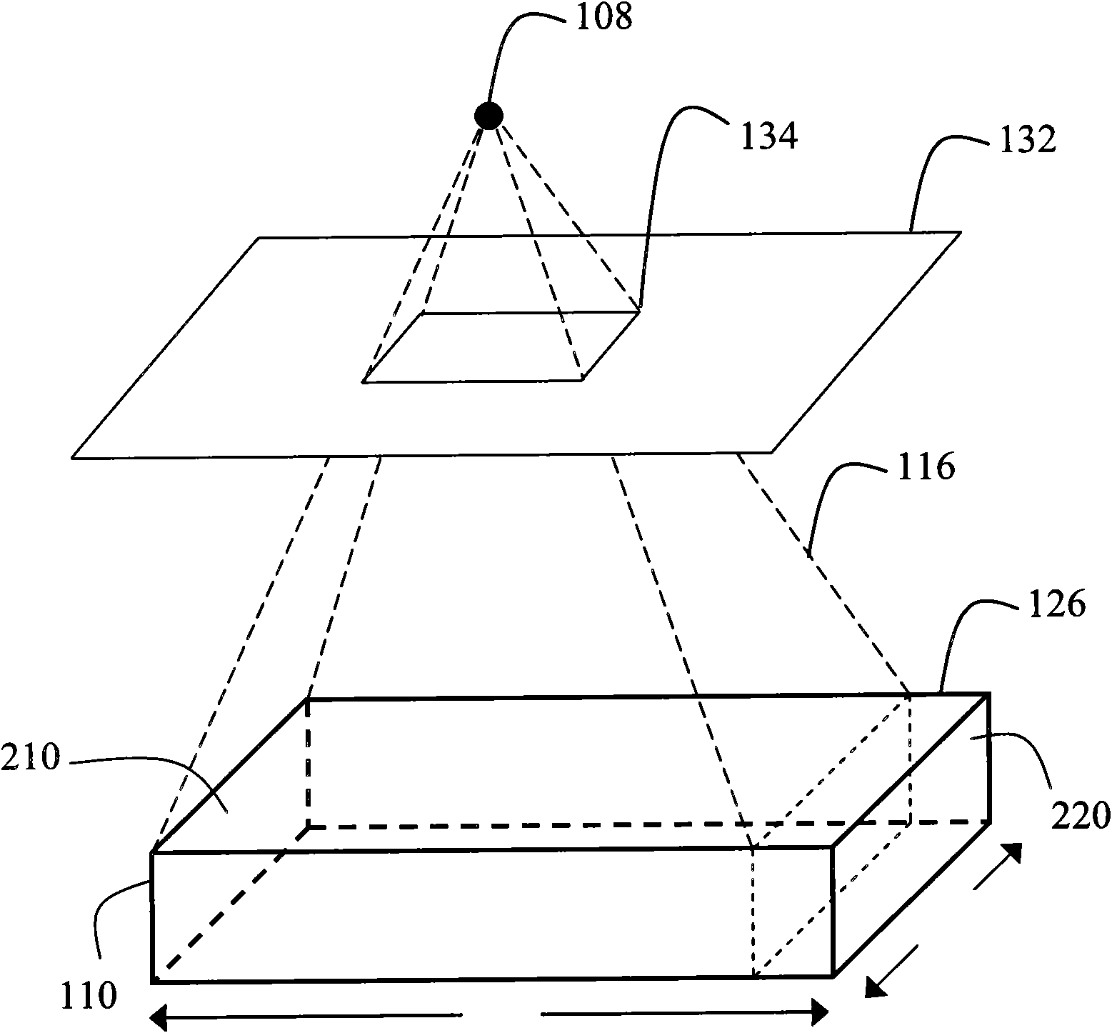
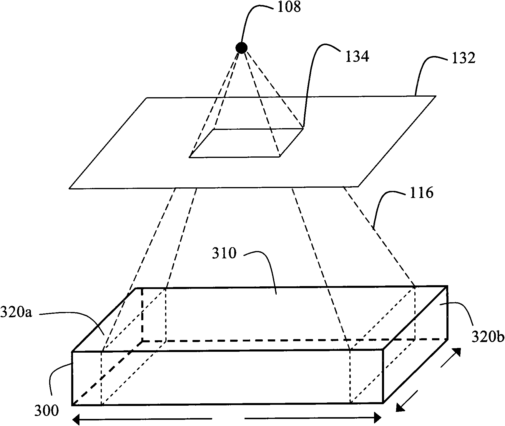
[0013] The imaging methods and apparatus of the present application relate generally to any imaging system that corrects for scattered photons. An example of such a device is figure 1 An imaging system 100 is shown in , which is particularly useful in generating CT images. As previously mentioned, the imaging methods and apparatus disclosed herein have application in various other kinds of imaging systems.

[0014] like figure 1 Illustratively, a bed or other suitable subject support 102 supports a subject 104 under examination within an examination region 106 . An X-ray source 108 such as an X-ray tube and an X-ray detector 110 such as a flat panel detector are provided. The X-ray source 108 and X-ray detector 110 are mounted on a common rotating gantry (not shown) having a center of rotation 112 . X-ray source 108 and X-ray detector 110 are rotated together with the gantry about support 102 and subject 104 being imaged. In this way, imaging measurements can be made of a...


PUM


Abstract

A method and apparatus of image reconstruction correcting for photon scatter is provided. A direct physical measurement of scattered photons is used in conjunction with a physical model of the photon scattering process to make the corrections.

Description

technical field [0001] The present application relates generally to imaging techniques, and more particularly to apparatus and methods for scattered photon correction. The present application is for X-ray imaging (using X-ray photons), computed tomography or CT imaging (using X-ray photons), and other kinds of systems such as image-guided radiation therapy systems. Background technique [0002] Such imaging processes typically include a radiation source that generates imaging photons. Photons pass through the subject being imaged and are collected or counted by photon detectors. The data generated by the photon detectors is then electronically processed to generate an image of the subject. Two types of photons reach the photon detector. The first is the "primary" photon, which is generated by the photon source and travels along a rectilinear path through the subject being imaged to reach the photon detector. The second is "scattered" photons, which include photons genera...

Claims


Application Information

Patent Timeline
Patent Type & Authority Applications(China)
IPC IPC(8): G06T11/00
CPCG06T11/005
Inventor M·贝尔特拉姆J·维格特S·G·赫曼
Owner KONINKLIJKE PHILIPS ELECTRONICS NV
Learn More