
Heat-exchange dedusting device

A technology of dust removal device and connection device, which is applied in the direction of heat exchanger type, indirect heat exchanger, lighting and heating equipment, etc., can solve the problems of dust can not be removed, single function, and the results of use cannot be achieved.

Inactive Publication Date: 2011-04-27
陈坤
View PDF0 Cites 0 Cited by
  • Summary
  • Abstract
  • Description
  • Claims
  • Application Information

AI Technical Summary

Problems solved by technology

[0002] At present, there are various heat exchange devices at home and abroad, their functions are single, and the effect is not very good, especially the dust in the smoke of the heat exchange devices used on boilers cannot be removed, causing air pollution
Some manufacturers also manufacture various exchange devices in order to achieve the purpose, but the cost is too high, and the result of use still fails to achieve the purpose

Method used


Image

  • Heat-exchange dedusting device
  • Heat-exchange dedusting device
  • Heat-exchange dedusting device

Examples


Embodiment Construction

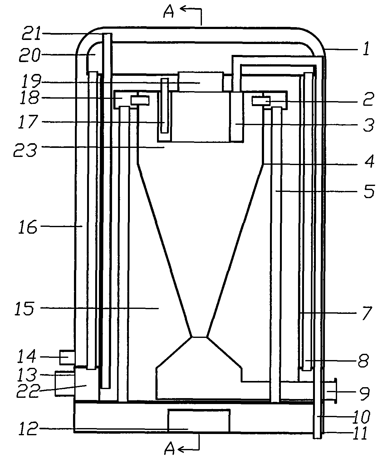
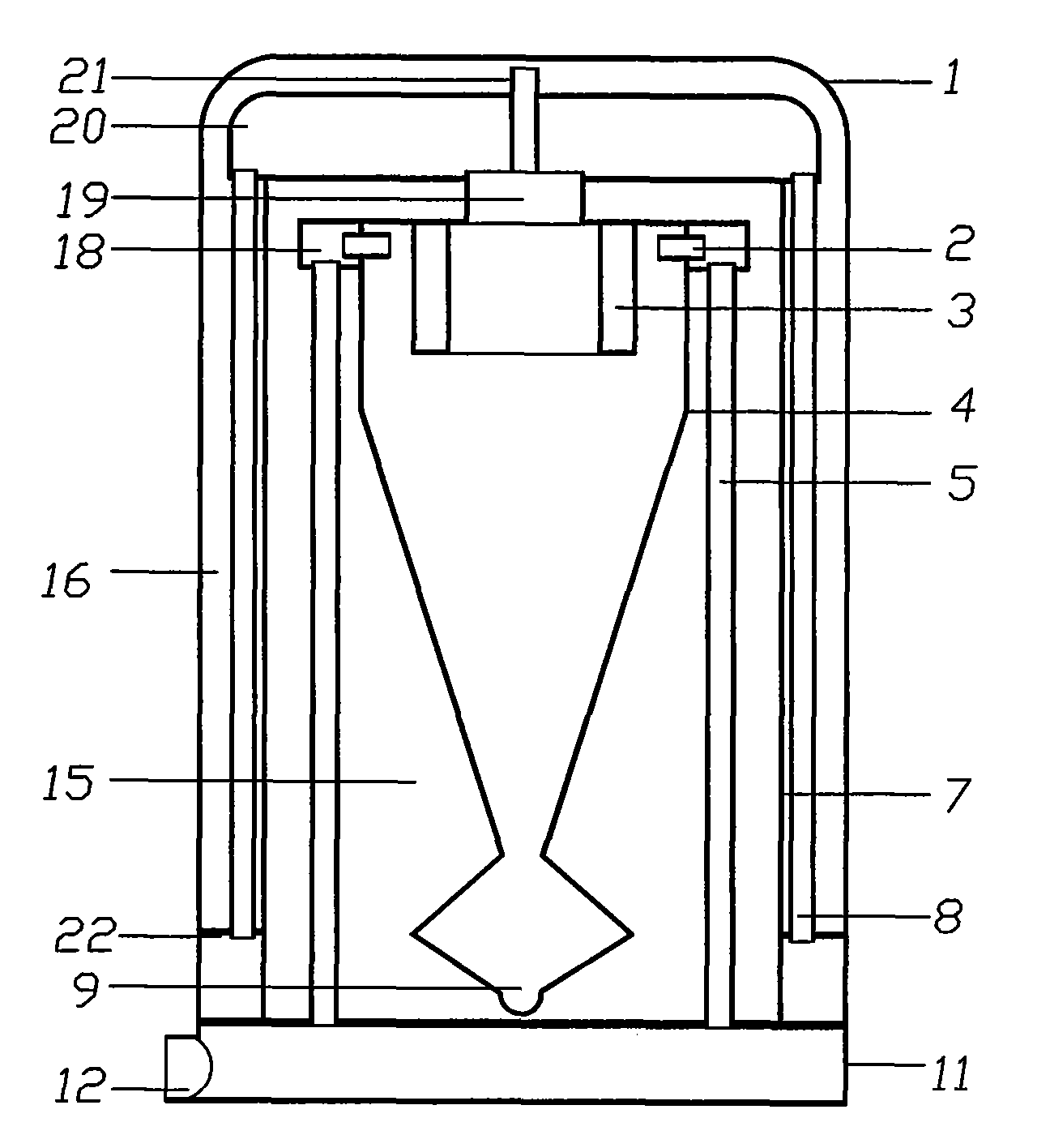
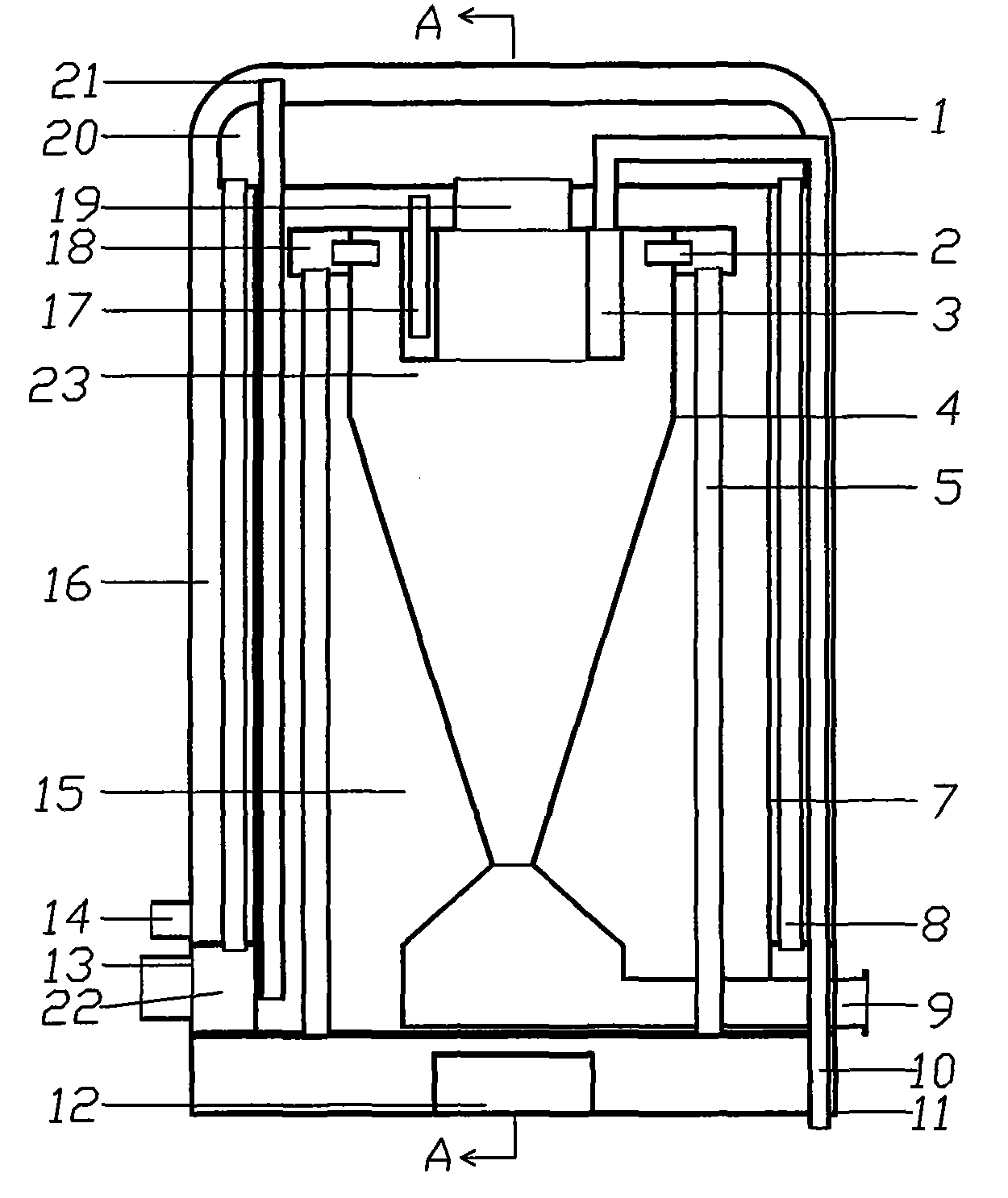
[0010] Such as figure 1 , figure 2 The shown heat exchange dedusting device includes a housing 1 with a connecting device 11 at the lower end of the housing, a hot gas inlet 12 on the connecting device 11, a water inlet 14 at the lower part of the housing, and a separation partition 7 inside the housing. The 7 separating partitions are the cold water area 16, and the inside of the separating partition is the warm water area 15. There is an upper smoke chamber 20 on the upper part of the shell, a lower smoke chamber 22 on the lower part of the shell, and a smoke outlet 13 on the lower smoke chamber. There is a dust removal device 4 inside, and there is a dust removal port 9 below the dust removal device. An isolation interlayer retaining ring 23 is installed on the upper part of the dust removal device. Inside the isolation interlayer retaining ring is a hot water area 3. The smoke outlet 19 of the dust removal device is located in the center of the isolation interlayer retain...


PUM


Abstract

The invention discloses a heat-exchange dedusting device. The heat-exchange dedusting device comprises a shell, wherein a connecting device is arranged at the lower end of the shell; the connecting device is provided with a hot air inlet; a water inlet is formed on the lower part of the shell; a separating baffle is arranged in the shell; a cold water area is formed between the shell and the separating baffle; a warm water area is formed in the separating baffle; an upper smog chamber is arranged on the upper part of the shell, and a lower smog chamber is arranged on the lower part of the shell; the lower smog chamber is provided with a fume outlet; and a dedusting device is arranged in the separating baffle. The heat-exchange dedusting device can be used as the upper half body of a boiler and also can connect the smoke outlet of the boiler with the fume inlet of the connecting device, most heat in hot fume is absorbed by water, and dust in the fume is removed by the dedusting device at the same time, so that the dual aims of surplus heat utilization and environmental emission are fulfilled.

Description

technical field [0001] The invention belongs to environmental protection equipment, in particular to a heat exchange dust removal device which integrates waste heat utilization and dust removal. Background technique [0002] There are various heat exchange devices at home and abroad at present, and its function is all single, and effect is not too good, especially the dust in the smoke of the heat exchange device used on the boiler can not be removed, pollutes the air. Some manufacturers have also manufactured various exchange devices in order to achieve the purpose, but the cost is too high, and the result of use still cannot reach the purpose. Contents of the invention [0003] The purpose of the present invention is to provide a heat exchange dust removal device, which can remove the dust in the gas while absorbing the heat in the hot gas. [0004] In order to achieve the above object, the present invention adopts the following technical solutions: a heat exchange dust...

Claims


Application Information

Patent Timeline
IPC IPC(8): F28D1/06F23J15/02
Inventor 陈坤
Owner 陈坤
Learn More