Capture hood

A technology for collection hoods and production equipment, applied in the field of collection hoods, which can solve the problems of small airflow slopes and the inability to realize obliquely upwardly directed airflows, and achieve the effect of improving efficiency

Active Publication Date: 2015-11-25
RENTSCHLER REVEN LUFTUNGSSYST
View PDF7 Cites 0 Cited by
  • Summary
  • Abstract
  • Description
  • Claims
  • Application Information

AI Technical Summary

Problems solved by technology

[0008] However, it has been found that with the known constructional measures it is hardly possible to achieve a substantially obliquely upwardly directed air flow, since for this the deflection of the air flowing from above into the air supply chamber has to be redirected at an acute angle.
Although curved deflection areas can have corresponding geometries, practice has shown that turbulent flow occurs and the inner radius of the deflection area largely impedes the flow, so that the air flow emerging from the outlet opening often has too little slope or even a slight dip

Method used


Image

  • Capture hood
  • Capture hood
  • Capture hood

Examples


Embodiment Construction

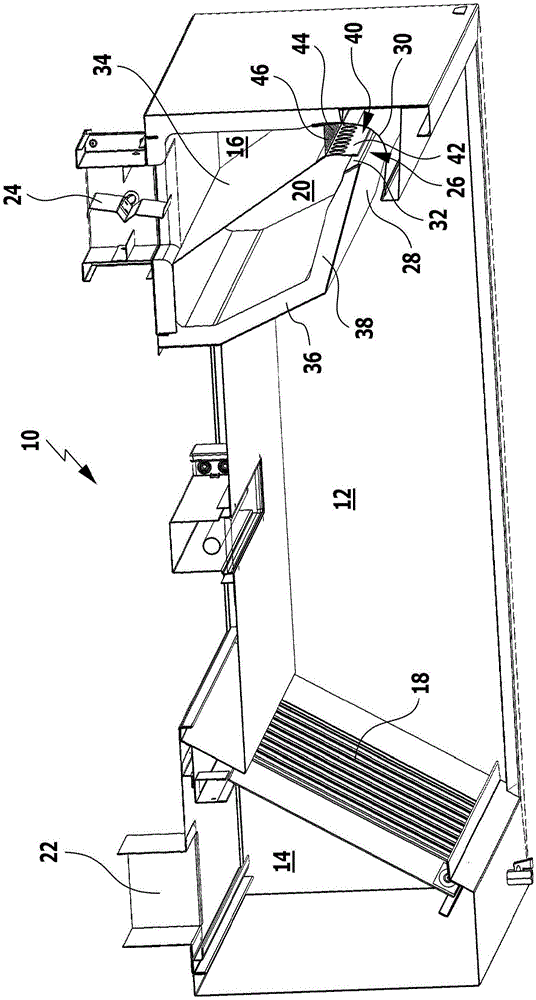
[0036] figure 1 A perspective view of an embodiment of a collecting hood according to the invention is shown, generally designated 10 . The collecting hood 10 itself extends in a longitudinal direction which extends approximately perpendicularly to the plane of the drawing. For better visibility, the figure 1 Only one section of the collecting hood 10 is shown in FIG.

[0037] The collecting hood 10 comprises a centrally arranged fume chamber 12 which is open downwards and tapers upwards. A suction chamber 14 and an air supply chamber 16 are arranged on both sides of the smoke chamber 12 , wherein the suction chamber 14 is separated from the smoke chamber 12 by a separator 18 and is arranged between the smoke chamber 12 and the air supply chamber 16 There is a low pressure chamber 20 . The smoke chamber 12 , the suction chamber 14 , the air supply chamber 16 and the low-pressure chamber 20 extend horizontally and parallel to one another in the longitudinal direction.

[0...


PUM


Abstract

The present invention relates to a capture hood for capturing the waste air above cooking points, production devices and the like, comprising a vapour chamber, a suction-extraction chamber and an air-supply chamber, said chambers extending horizontally and parallel to one another in a longitudinal direction, wherein - the vapour chamber is open at the bottom and tapers toward the top, - the suction-extraction chamber is separated from the vapour chamber by a filter or a separator, wherein the filter or the separator forms an inclined boundary of the vapour chamber which tapers toward the top, and - the air-supply chamber tapers toward the bottom and merges at its lower end with a curved deflection region which issues into a blow-out opening which is arranged at the lower end of the vapour chamber opposite the suction-extraction chamber such that feed air which is blown into the air-supply chamber from above exits from the blow-out opening horizontally or obliquely upward in the direction of the filter or of the separator. The capture hood further comprises a negative-pressure chamber which is arranged between the vapour chamber and the air-supply chamber, wherein the negative-pressure chamber is closed on all sides with the exception of a suction opening at its lower end, said suction opening issuing, in the region of the inside radius of the curved deflection region of the air-supply chamber, into said deflection region, and wherein the negative-pressure chamber and the air-supply chamber are separated from one another along an induction region, which adjoins the suction opening or the deflection region at the top, by a wall which has a plurality of individual apertures which are arranged in succession in the longitudinal direction of the capture hood.

Description

technical field [0001] The invention relates to a collecting hood for collecting exhaust gases above hobs, production plants and the like, comprising a fume chamber, a suction chamber and an air delivery chamber extending horizontally and parallel to each other in longitudinal direction ,in, [0002] - the smoke chamber is open downwards and tapers upwards, [0003] - the suction chamber is separated from the smoke chamber by a filter or a separator, wherein the filter or separator forms an oblique delimitation of the smoke chamber which narrows upwards, and [0004] - The air delivery chamber narrows downwards and merges at its lower end into a curved deflection region which opens into a blow-out opening which is arranged at the lower end of the smoke chamber relative to the suction chamber as follows Up, that is to say, the conveying air blown into the air conveying chamber from above is discharged from the outlet opening horizontally or obliquely upwards in the direction ...

Claims


Application Information

Patent Timeline
Patent Type & Authority Applications(China)
IPC IPC(8): F24C15/20B08B15/02
CPCF24C15/20F24C15/2035F24C15/2042
Inventor 斯文·兰特希勒
Owner RENTSCHLER REVEN LUFTUNGSSYST
Why Eureka
Try Eureka