
Liquid crystal display source electrode driving device and driving method thereof

A liquid crystal display, source drive technology, applied in static indicators, instruments, etc., can solve problems such as poor brightness, achieve the effect of meeting different requirements, solving poor brightness, and avoiding dark lines

Active Publication Date: 2011-04-20
BOE TECH GRP CO LTD +1
View PDF6 Cites 13 Cited by
  • Summary
  • Abstract
  • Description
  • Claims
  • Application Information

AI Technical Summary

Problems solved by technology

[0005] The technical problem to be solved by the present invention is to provide a liquid crystal display source driving device and driving method, which can select the best charging rate and optimize power consumption, effectively solve the problem of poor brightness, and avoid the dark line (Dim Line) phenomenon

Method used


Image

  • Liquid crystal display source electrode driving device and driving method thereof
  • Liquid crystal display source electrode driving device and driving method thereof
  • Liquid crystal display source electrode driving device and driving method thereof

Examples


Embodiment 1

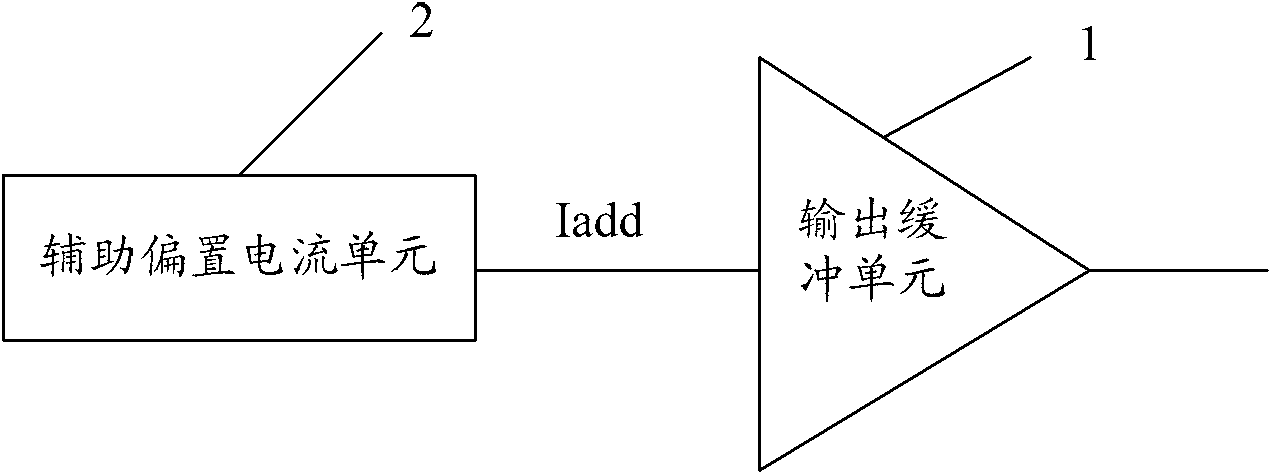
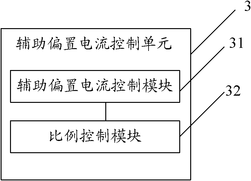
[0038] like figure 2 As shown, the embodiment of the present invention provides a liquid crystal display source driving device including: an output buffer unit 1 and an auxiliary bias current unit 2, and also includes: controlling the auxiliary bias current unit 2 to select from the output buffer unit 1 An auxiliary bias current control unit 3 that provides a dynamic auxiliary bias current Iadd.

[0039] Wherein, the liquid crystal display is in 2-line or 2+1-line inversion mode, then in the second line of two-line inversion, the auxiliary bias current control unit 3 controls the auxiliary bias current unit 2 to When the first row of the two rows is reversed, the auxiliary bias current Iadd provided for the output buffer unit 1 is A, and the auxiliary bias current control unit 3 controls the auxiliary bias current unit 2 in the reversed state of the two rows. In the second row, the magnitude of the auxiliary bias current Iadd provided for the output buffer unit 1 is B, and A...


PUM


Abstract

The embodiment of the invention discloses a liquid crystal display source electrode driving device and a driving method thereof, relating to the field of a liquid crystal display. In the invention, the optimal charging rate and the optimized power can be chosen to effectively solve the problem of brightness difference and avoid the phenomenon of dim line. The liquid crystal display source electrode driving device comprises an output buffer unit, an assistant bias current unit and an assistant bias current control unit, wherein the assistant bias current control unit controls the assistant bias current unit to provide dynamic assistant bias current for the output buffer unit. The invention can be applied to the liquid crystal display.

Description

technical field [0001] The invention relates to the field of liquid crystal displays, in particular to a source driving device and a driving method of a liquid crystal display. Background technique [0002] During the working process of the liquid crystal display panel, due to the stray capacitance such as parasitic capacitance (Cgd) in the sub-pixel unit, the output buffer unit of the source driver must charge the liquid crystal capacitance and storage capacitance at the same time. Part of the stray capacitance is charged. Therefore, the inversion mode of the dot inversion (DOT Line) has a large power consumption. [0003] At present, the inversion method of 2 lines (2Line) or 1+2 lines (1+2Line) is usually used to save power consumption, but at the same time of saving power consumption, since the output buffer unit pair Two lines with the same polarity require different power, that is, the power required to charge the stray capacitance when charging the second line is les...

Claims


Application Information

Patent Timeline
Patent Type & Authority Applications(China)
IPC IPC(8): G09G3/36
Inventor 罗红磊于杨冰
Owner BOE TECH GRP CO LTD
Learn More