
Calibration method of magnetic induction effect angle sensor

An angle sensor and calibration method technology, applied in the direction of instruments, electromagnetic means, measuring devices, etc., can solve the problems of not considering temperature changes, invisible, and complex calibration process.

Active Publication Date: 2011-04-20
昌辉汽车电气系统(安徽)有限公司 +1
View PDF9 Cites 16 Cited by
  • Summary
  • Abstract
  • Description
  • Claims
  • Application Information

AI Technical Summary

Problems solved by technology

[0007] There are many parameters to be calibrated, and the calibration process is relatively complicated, and the calibration compensation algorithm with good practical value is not found in existing patented inventions and papers
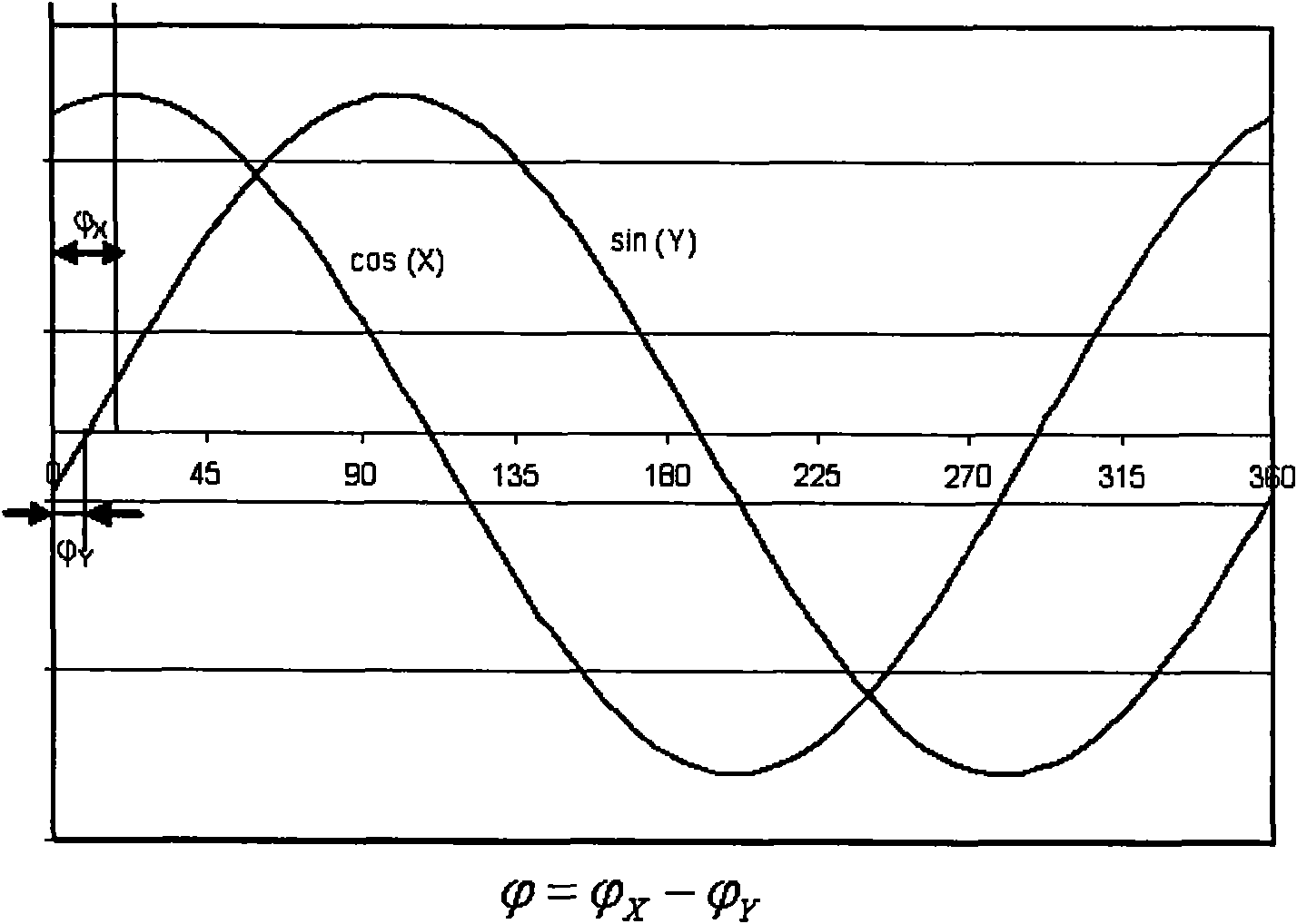
In 2002, Bosch company applied for the patent US 6494784B1 in the United States through three test points, which can compensate the offset of the output value of the magnetic induction chip of the magnetic induction effect angle sensor. The basic principle is to calculate the position of the center of the circle through three points on the circumference , this method can only obtain the offset, but does not involve the peak value of the output value of the magnetic induction chip, the phase difference of the output value of the magnetic induction chip, and the temperature coefficient of the offset
[0034] The calibration formula given in the chip application manual is only for a single magnetic induction chip, and does not consider the temperature change during the calibration process. There is no explanation for the calibration of a complete angle sensor composed of multiple magnetic induction chips.

Method used


Image

  • Calibration method of magnetic induction effect angle sensor
  • Calibration method of magnetic induction effect angle sensor
  • Calibration method of magnetic induction effect angle sensor

Examples


Embodiment Construction

[0053] The calibration method of the magnetic induction effect angle sensor that the present invention proposes is described in detail as follows in conjunction with accompanying drawing and embodiment:

[0054] The specific implementation device and connection for the calibration method of the present invention are as follows: Image 6 As shown, the calibration process is realized with the cooperation of the calibration system with the magnetic induction effect angle sensor to be calibrated (hereinafter referred to as the angle sensor). The calibration system consists of a calibration system controller, a motor driver, and a motor. The calibration system controller is responsible for controlling the power on of the angle sensor, communicating with the angle sensor and controlling the rotation of the motor. The motor is a stepper motor or a servo motor. During the calibration process, the shell of the angle sensor is fixed relative to the shell of the motor in the calibration ...


PUM


Abstract

The invention relates to a calibration method of a magnetic induction effect angle sensor, belonging to the technical field of sensors test and measurement. The method comprises a plurality of sub-calibration processes of a low-temperature segment calibration process and a high-temperature segment calibration process, wherein each sub-calibration process comprises the following steps that: for the calibration of a first calibration test point of a first chip: a calibration system controller first controls a motor to input a rotation angle into the rotation direction of the first calibration test point; the calibration system sends a rotating in-place instruction; the angle sensor collects and processes relevant data when detecting the instruction; and the calibration system rotates for a unit step length and cycles accordingly until the calibration of all calibration test points is completed after receiving the instruction. The calibration method can realize the operation inside the angle sensor, substantially improves the angle measuring precision of the magnetic induction effect angle sensor through the calibration, and is applied to the quick and accurate calibration of the magnetic induction effect angle sensor during the mass production.

Description

technical field [0001] The invention belongs to the technical field of test and measurement sensors, in particular to the calibration of a magnetic induction effect angle sensor. Background technique [0002] With the development of industrial automation, automotive electric power steering, and automotive electronic stability control, there are more and more applications of angle sensors. The magnetic induction effect has good application value and practical prospect due to its good characteristics such as non-contact, good hysteresis characteristics, and anti-environmental interference, and has been widely used in automobiles. [0003] There are many forms of magnetic induction effect angle sensors, and their basic components are as follows: figure 1 shown. It consists of a housing 1, a rotating input gear 2, one or more driven gears 3, a magnet 4 fixedly connected to the driven gears, a magnetic induction chip 5, a single-chip microcomputer 6, a power supply module 7, an...

Claims


Application Information

Patent Timeline
Patent Type & Authority Applications(China)
IPC IPC(8): G01B7/30
Inventor 宋健李红志于良耀李亮王进丁汪春华李东兵王伟玮王治中吴凯辉
Owner 昌辉汽车电气系统(安徽)有限公司
Learn More