Eureka AIR delivers breakthrough ideas for toughest innovation challenges, trusted by R&D personnel around the world.

Magnetic levitation steering mechanism

A technology of steering mechanism and magnetic levitation, which is applied to devices that move laterally between the chassis and the bogie, electric traction, electric vehicles, etc. It can solve problems such as complex mechanisms, increased manufacturing and maintenance costs, and vibrations, and reduce manufacturing costs. and maintenance costs, prolonging the service life, and reducing the effect of additional force

Active Publication Date: 2012-07-25
CRRC TANGSHAN CO LTD +2
View PDF0 Cites 0 Cited by
  • Summary
  • Abstract
  • Description
  • Claims
  • Application Information

AI Technical Summary

Problems solved by technology

To achieve this relative movement (rail, bogie, car body) must solve the following problems: 1) The bogie must fit the track to obtain the maximum suspension force and maintain the direction of motion; 2) The bogie and the car must maintain a certain relative Positional relationship to prevent unbalanced load; 3) The bogie needs to drive the car body to deflect and change the direction of motion, so there must be a connection point between the bogie and the car body, and this connection cannot limit the freedom of the bogie to run along the track
[0014] 1. When the train passes the curved track, the two displacements produced by the air spring must be compensated, and the trajectory is not the real trajectory of the end, which is prone to additional vibration;
[0015] 2. Generate additional force, affecting the flexibility of bogie rotation;
[0016] 3. Lead to complex mechanism, increase manufacturing and maintenance costs

Method used


Image

  • Magnetic levitation steering mechanism
  • Magnetic levitation steering mechanism
  • Magnetic levitation steering mechanism

Examples


no. 1 example

[0060] refer to Figure 6-1 , shows a schematic diagram of the first embodiment of the magnetic levitation steering mechanism of the present invention. The above magnetic levitation steering mechanism is an arc-shaped moving slide table, including: a first raceway body 601 and a first roller seat 602 . Wherein, the first raceway body 601 is connected with the vehicle body as the upper part of the arc-shaped motion slide table; the first roller seat 602 is connected with the bogie as the lower part of the arc-shaped motion slide table; the first raceway body 601 is connected with the first roller The sub-seat 602 is in contact and moves in a relative circular arc. The first roller seat 602 and the first raceway body 601

[0061] For details, see Figure 6-2 The schematic diagram of the first raceway body is shown, and the plane where the first raceway body 601 is in contact with the first roller seat 602 is defined here as the first lower plane 6011 of the first raceway body ...

no. 2 example

[0065] refer to Figure 6-4 Shown is the cross-sectional view of the second embodiment of the magnetic levitation steering mechanism of the present invention. The arc-shaped movement slide type magnetic levitation steering mechanism includes: a second roller seat 61 , a second raceway body 63 and two connecting positioning devices 62 .

[0066] The components of Embodiment 2 of the magnetic levitation steering mechanism of the present invention will be described in detail below in conjunction with the specific structural diagrams of each part.

[0067] 1. Example of roller seat

[0068] refer to Figure 7 In the schematic structural view of the embodiment of the roller seat shown, the second roller seat 61 is composed of a roller seat body 71 and several rollers 72 . In this embodiment, three rollers 72 are arranged on the roller seat body 71 . The three rollers 72 are evenly arranged on the roller seat body 71 in a fan shape. Figure 8 A schematic diagram of the working a...

no. 3 example

[0088] refer to Figure 14 As shown, it shows a schematic diagram of the third raceway body of the magnetic levitation steering mechanism of the present invention. The difference from the second embodiment of the magnetic levitation steering mechanism is that the third upper plane 6111 of the third raceway body 611 in this embodiment is one side is a straight line, and the other side is a plane of an arc. Figure 15 The shown cross-sectional view of the third raceway body 611 along the direction A-A shows that the third raceway body 611 has a half I-shaped structure. The connection relationship between the entire magnetic levitation mechanism and the car body is as follows: Figure 16 As shown, the third upper plane 6111 of the third raceway body 611 is fixedly connected to the car body 600, and the connection relationship of other components is the same or similar to that of the second embodiment, and will not be repeated here.


PUM


Abstract

The invention provides a magnetic levitation steering mechanism which is installed between a vehicle body and a steering frame of a magnetic levitation vehicle, and the steering mechanism is an arc movable sliding table, wherein the upper part of the sliding table is connected with the vehicle body, and the lower part of the sliding table is connected with the steering frame; the upper part and the lower part of the sliding table make relative movement with a circular arc movement trail. The arc movable sliding table specifically includes: a roller seat and a rollway body, wherein the rollway body is connected to the vehicle body as an upper part of the sliding table, the roller seat is connected to the steering frame as a lower part of the sliding table; the rollway body is in an arc structure of which an upper flat surface is fixedly connected to the vehicle body and a lower flat surface is in contact with the roller seat, the two moving relatively in a circular arc track. The introduction of the magnetic levitation steering mechanism realizes that a moving point of a steering module forming the steering frame makes arc movement around a relative rest point to drive the vehicle body and the steering frame to make circular arc relative movement together, so that the vehicle passes through a curve track smoothly, and the service life of an air spring and the steering frame is prolonged.

Description

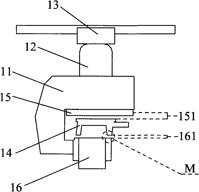
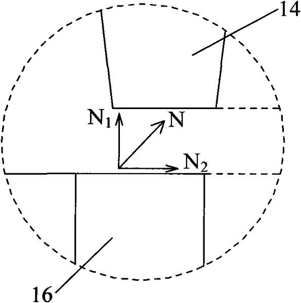
technical field [0001] The invention relates to the technical field of magnetic levitation vehicles, in particular to a magnetic levitation steering mechanism for a magnetic levitation train. Background technique [0002] Maglev train is a train propelled by magnetic levitation force (that is, magnetic attraction or repulsion force). Due to the magnetic force of its track, it is suspended in the air and does not need to touch the ground when walking, so its resistance is only the resistance of the air. The maximum speed of the maglev train can reach more than 500 kilometers per hour. It has high speed, low noise, environmental protection, economy and comfort. Features. [0003] refer to Figure 1-A The schematic diagram of the structure of the magnetic levitation train steering device shown and Figure 1-B shown Figure 1-A The enlarged view of the middle part M and its force schematic diagram. The bogie frame 11 is installed on the track 14, the bogie frame 11 is provide...

Claims


Application Information

Patent Timeline
Patent Type & Authority Patents(China)
IPC IPC(8): B61F5/02B60L13/06
Inventor 赵志苏郑宝奎高晓霞王永刚
Owner CRRC TANGSHAN CO LTD
Why Eureka
Eureka Blog
Learn More