
Phase combination fault detection method of traffic signal controller

A phase combination and fault detection technology, applied in traffic control systems, traffic signal control, road vehicle traffic control systems, etc., can solve the problem of not providing a specific method for signal lamp phase combination fault detection.

Inactive Publication Date: 2011-04-13
SICHUAN NEW DEV TECH
View PDF2 Cites 18 Cited by
  • Summary
  • Abstract
  • Description
  • Claims
  • Application Information

AI Technical Summary

Problems solved by technology

However, in the existing settings or methods, there is no specific method for the detection of other signal lamp phase combination faults other than green conflict detection.

Method used


Image

  • Phase combination fault detection method of traffic signal controller
  • Phase combination fault detection method of traffic signal controller
  • Phase combination fault detection method of traffic signal controller

Examples


Embodiment 1

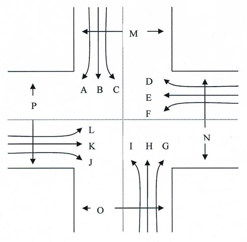
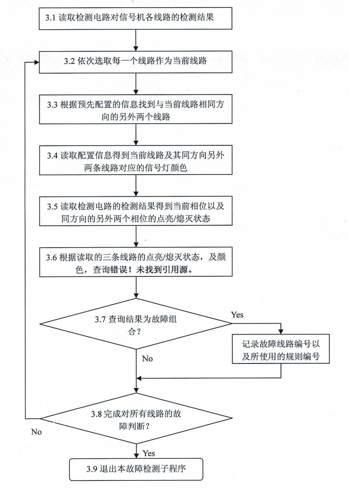
[0062] Embodiment 1: Assume that the traffic signal controller fails, causing the red light, yellow light, and green light of direction B to be turned on at the same time. This will cause vehicles in direction B to stop for a long time or drive in confusion due to contradictory signal lights. When a fault occurs, when the software program of the present invention is executed to step 3) when processing line 2, it will determine that the direction corresponding to line 2 is direction B according to the information configured in Table 4, and the signal light in this direction is: line 2 red light , Line 18 green light, line 34 yellow light. In step 4), the detection result of the reading detection circuit is that the red light (line 2) is on, the green light (line 18) is on, and the yellow light (line 34) is on. In step 5), use rule 1 in Table 1 to judge that this is a fault combination, then record the fault lines as line 2, line 18 and line 34, and the fault rule is rule 1.

Embodiment 2

[0063] Embodiment 2. It is assumed that the traffic signal controller fails, causing when the red light in the direction E goes out, the red light in the direction B that crosses it also goes out at the same time. This will cause vehicles in the two crossing directions to pass at the same time because there is no red light indication, causing congestion and confusion at the intersection. When a fault occurs, when the software program of the present invention is executed to step 8) when processing line 2, it will determine that line 2 is a red light according to Table 4 of the embodiment according to the configuration information in Table 4, and the corresponding direction is B. In step 9) through the configuration information in Table 3, determine that direction E is the first direction that intersects with direction B, and determine that the red light line number in direction E is 5 according to the configuration information in Table 4. In step 10), the detection result of th...


PUM


Abstract

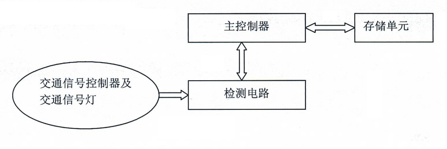
The invention discloses a phase combination fault detection method of a traffic signal controller, which relates to the technical field of traffic signal control and computer application. In the method, support hardware and a program module are adopted; and the support hardware at least comprises a master controller, a storage unit and a detection circuit. The method is characterized in that the storage unit stores a predefined congruent relationship list and a predefined fault rule list, the program module carries out steps of detecting and discriminating the phase combination fault, and the specific steps are as follows: detecting whether a signal lamp on each circuit is in a lightening or extinguishing state by using a current or voltage detection circuit; and discriminating whether abnormal combination of lightening or extinguishing of the signal lamp on each circuit at any time exists. By utilizing the method, the phase combination fault of a plurality of traffic signal control systems can be detected, and the phase combination fault of the traffic signal control systems can be effectively and automatically found out and reported.

Description

technical field [0001] The invention belongs to the technical field of traffic electronic signal control and computer software application, in particular to a traffic signal controller phase combination fault detection method. Background technique [0002] The normal work of the traffic signal system plays an important role in maintaining the normal order of urban traffic. When the traffic signal system fails, it often leads to traffic chaos or a decrease in the efficiency of vehicle traffic. Therefore, it is of great significance to discover and deal with traffic signal system failures in time for modern traffic management. For the fault judgment of the traffic signal signal system, it is usually to detect the faults that can be judged based on the individual state of each phase, such as damage to the signal lamp, short circuit of the line, short circuit damage of the line, etc. However, in the actual use process, there are phase combination failures caused by signal cont...

Claims


Application Information

Patent Timeline
IPC IPC(8): G08G1/07G08G1/095
Inventor 王竞
Owner SICHUAN NEW DEV TECH
Learn More