Method for testing dynamic lock area of prismatic laser gyro

A technology of laser gyro and testing method, which is applied in the testing/calibration of speed/acceleration/shock measurement equipment, measurement device, speed/acceleration/shock measurement, etc., can solve the problems of low work efficiency, waste of human resources, large error, etc. , to achieve the effect of improving production efficiency and facilitating production and application

Active Publication Date: 2011-04-13
西安北方捷瑞光电科技有限公司
View PDF3 Cites 9 Cited by
  • Summary
  • Abstract
  • Description
  • Claims
  • Application Information

AI Technical Summary

Problems solved by technology

There are two main problems: 1) The error is large. The rotation rate of the turntable is controlled manually and is completely in a random state. The test accuracy is only 0.03° / s, and it is impossible to judge the time when the minimum lock value is generated. As a result, it is impossible to determine whether the tested lock area value is the minimum lock area value; 2) the work efficiency is low, and the conservative time for a lock area test is 2 hours, and a dedicated person is required to observe the operation all the time during the whole process, which wastes human resources

Method used


Image

  • Method for testing dynamic lock area of prismatic laser gyro
  • Method for testing dynamic lock area of prismatic laser gyro
  • Method for testing dynamic lock area of prismatic laser gyro

Examples


Embodiment Construction

[0019] When the prism laser gyro is working normally, when the rotation angular velocity is less than a certain critical value, the pulse signal output by the prism laser gyro has no response to the change of the rotation angular velocity. The critical angular velocity is the dynamic locking area of ​​the laser gyro.

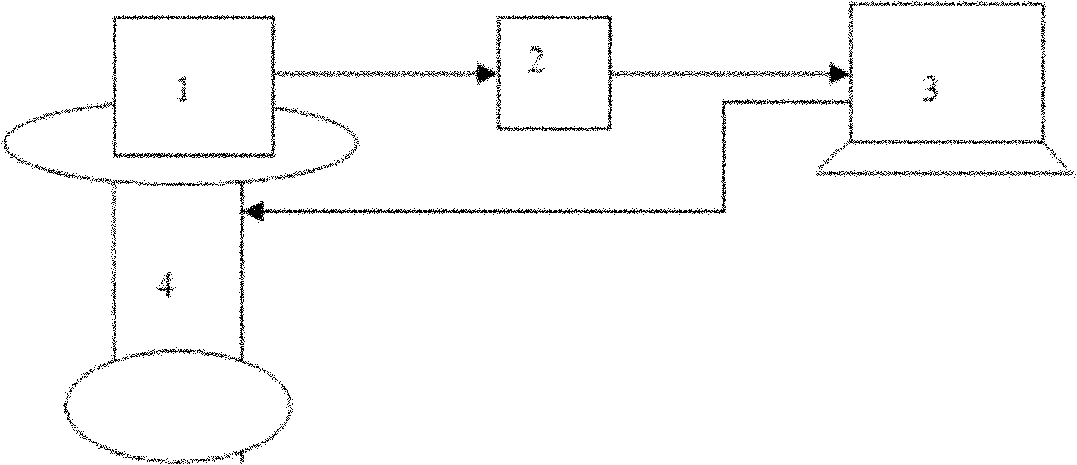
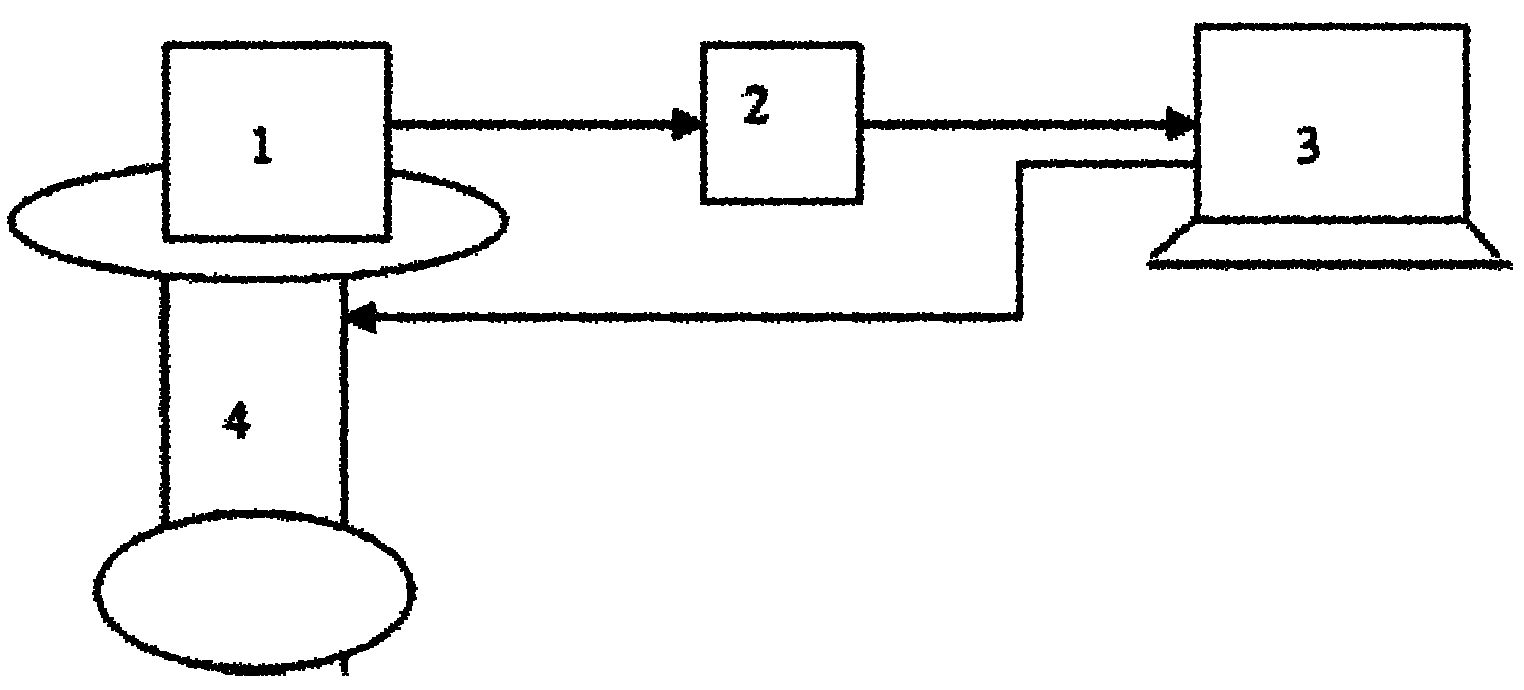
[0020] see figure 1 Shown, the test device of a kind of prism-type laser gyro dynamic locking area test method of the present invention comprises measured laser cavity 1, signal receiving and processing device 2 (comprising photoelectric receiver, signal amplifier, rectifying filter), sampling and Analysis device 3 (single chip microcomputer) and rate turntable 4.

[0021] The prism-type laser resonator 1 is fixed on the single-axis rate turntable 4, the laser resonator 1 is excited to emit light by an external power supply, and the photoelectric receiver of the signal receiving and processing device 2 is aligned with the P-polarized light emitted by the laser r...


PUM


Abstract

The invention relates to a method for testing a dynamic lock area of a prismatic laser gyro. The method comprises the following steps: 1) motivating a laser gyro to emit P polarized lights; 2) starting a rotary table to rotate according to a cosine curve equation; 3) aligning a photoelectric receiver at the P polarized lights so as to receive light pulse signals, and then converting the light pulse signals into electrical signals; 4) amplifying the electrical signals; 5) rectifying and filtering the amplified electrical signals, then converting the electrical signals into square signals, and inputting the square signals into a microcontroller; 6) reading the number of pulse in the square signals in real time and acquiring the angular velocity of rotation of the rotary table by the microcontroller, and inputting the obtained related information into an image display device; 7) displaying a relationship chart relating to the number of pulse, the angular velocity of rotation and the time in real time by the image display device; and 8) reading the angular velocity (namely, the value of the dynamic lock area of the detected prismatic laser gyro) of rotation of the rotary table corresponding to the time when the pulse signal in the relationship chart occurs. The method provided by the invention has the advantages of quickly and accurately realizing the detection on the lock areas, rapidly increasing the production efficiency, and facilitating the production application and the quality judgment of a laser resonant cavity.

Description

【Technical field】 [0001] The invention relates to the technical field of testing, in particular to a prism-type laser gyroscope dynamic area-locking testing method. 【Background technique】 [0002] As a unique type of laser gyro, the prism laser gyro is only produced in Russia abroad. The test of the locked area is completed by the traditional manual turntable and photoelectric receiver. There are two main problems: 1) The error is large. The rotation rate of the turntable is controlled manually and is completely in a random state. The test accuracy is only 0.03° / s, and it is impossible to judge the time when the minimum lock value is generated. As a result, it is impossible to determine whether the tested lock area value is the minimum lock area value; 2) The work efficiency is low, and the conservative time for a lock area test is 2 hours, and a dedicated person is required to observe the operation all the time during the whole process, which wastes human resources . 【Co...

Claims


Application Information

Patent Timeline
Patent Type & Authority Applications(China)
IPC IPC(8): G01C25/00G01P21/00
Inventor 石念宝刘卓
Owner 西安北方捷瑞光电科技有限公司
Why Eureka
Try Eureka