
Reducer bearing lubricating device, reducer using same and lower case of device

A technology of lubricating device and reducer, which is applied in the direction of gear lubrication/cooling, transmission box, components with teeth, etc., to reduce the temperature of the working surface, prolong the fatigue life, and eliminate the effect of frictional heat

Inactive Publication Date: 2011-04-13
CNR LANZHOU LOCOMOTIVE
View PDF5 Cites 5 Cited by
  • Summary
  • Abstract
  • Description
  • Claims
  • Application Information

AI Technical Summary

Problems solved by technology

[0007] The present invention provides a lubricating device for reducer bearings to solve the above-mentioned problems of the existing lubricating devices for reducer bearings

Method used


Image

  • Reducer bearing lubricating device, reducer using same and lower case of device
  • Reducer bearing lubricating device, reducer using same and lower case of device
  • Reducer bearing lubricating device, reducer using same and lower case of device

Examples


Embodiment Construction

[0024] The manufacturing method of the metal component of the present invention will be described in detail below in conjunction with specific embodiments and accompanying drawings. In the following description, numerous specific details are set forth in order to provide a thorough understanding of the present invention. However, the present invention can be implemented in many other ways different from those described here, and those skilled in the art can make similar extensions without violating the connotation of the present invention, so the present invention is not limited by the specific implementations disclosed below.

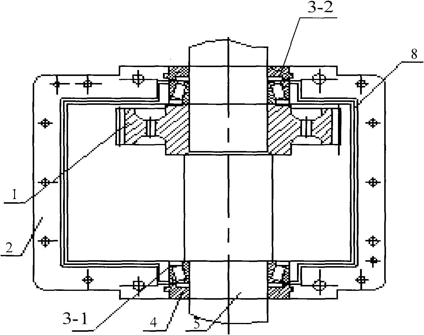
[0025] The lubricating device of the reducer bearing of the present invention will be described in detail below in conjunction with the accompanying drawings. image 3 It is a structural schematic diagram of a reducer applying the reducer bearing lubricating device of the present invention; Figure 4 It is a structural schematic diagram of the lower c...


PUM


Abstract

The invention provides a reducer bearing lubricating device, a reducer using the same and a lower case of the device. The reducer bearing lubricating device comprises an oil receiving tray, an oil storage tank and an oil guide tank, wherein the oil receiving tray is arranged on the side wall of the lower case of the reducer, the oil storage tank is arranged at the end part in the lower half hole of the front bearing hole, and the oil guide tank is arranged along the side wall of the lower case and is connected with the oil receiving tray and the oil storage tank; and the oil pan is arranged at a position on the side wall of the lower case that lubricating oil of the lower case can be splashed to the oil receiving tray by the rotation of the reducer gear, thereby ensuring the reliable and normal operation.

Description

technical field [0001] The invention relates to the technical field of reducer bearings, in particular to a lubricating device for reducer bearings. At the same time, the invention also relates to a speed reducer and a lower box thereof using the lubricating device for the speed reducer bearing. Background technique [0002] The reducer refers to the transmission device between the prime mover and the working machine, which is used to reduce the speed and increase the torque accordingly. The reducer can be divided into gear reducer, worm reducer and planetary gear reducer according to the structure. [0003] Gear reducer is a kind of reducer widely used in locomotives. Gear reducers include cylindrical gear reducers, bevel gear reducers, and conical-cylindrical gear reducers. Among them, the conical-cylindrical gear reducer is a two-stage reducer, which can generally transmit in both directions. The first stage is for conical gear transmission, and the second stage is for...

Claims


Application Information

Patent Timeline
IPC IPC(8): F16H57/04F16H57/02
Inventor 俞长英罗富兴
Owner CNR LANZHOU LOCOMOTIVE
Learn More