Tool for rotary cutting machining

A technology for cutting and cutting tools, which is applied in the field of replaceable cutting heads, tool bodies and cutting heads, and can solve the problems of high surface tolerance requirements and troubles

Inactive Publication Date: 2011-04-06
SECO TOOLS AB
View PDF2 Cites 17 Cited by
  • Summary
  • Abstract
  • Description
  • Claims
  • Application Information

AI Technical Summary

Problems solved by technology

The disadvantage of these tapered clamping surfaces is that the tolerances on these surfaces are very high and it is cumbersome to achieve these tolerances by machining

Method used


Image

  • Tool for rotary cutting machining
  • Tool for rotary cutting machining
  • Tool for rotary cutting machining

Examples


Embodiment Construction

[0029] The tool 1 of the present invention is intended to rotate, for the machining of workpieces. In the example shown, the tool is designed as an auger, but it is also possible to design the tool according to the invention as another tool for rotary cutting machining, for example a milling cutter or the like.

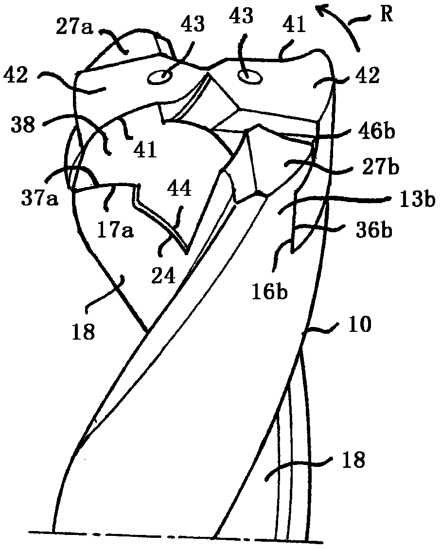
[0030] The intended direction of rotation of tool 1 for machining is in figure 2 , Figure 4 as well as Figure 11-12 Marked by arrow R. This direction of rotation is hereinafter named "rotary machining direction" and thus constitutes the direction of rotation in which the tool rotates for cutting machining of workpieces, preferably metal. Alternatively, the workpiece can be rotated while the tool remains stationary.

[0031] The tool 1 comprises a tool body 10 and a replaceable cutting head 30 detachably attachable to the tool body.

[0032] The cutting head 30 is formed in one piece of suitable cemented carbide, ie made of pressed or injection molded cemented ...


PUM


Abstract

The invention relates to a tool for rotary cutting machining, comprising a tool body (10) and a replaceable cutting head (30) de- tachably attachable to the tool body. At its front end, the tool body is provided with two coupling legs (13a, 13b) projecting in axial direction. The respective coupling leg is provided with a stop surface (16a, 16b) for transferring torque from the tool body to the cutting head, which stop surface is designed for abutment against a corresponding stop surface (36a, 36b) of the cutting head. The respective coupling leg is provided with a shoulder (26a, 26b) protruding from the stop surface of the coupling leg. The cutting head is provided with two shoulders (46a, 46b) facing the front end of the cutting head and arranged on opposite sides of the centre axis of the cutting head, which shoulders border on a respective one of said stop surfaces of the cutting head and are arranged to extend in under a respective one of said shoulders of the coupling legs of the tool body when the cutting head is attached to the tool body, so as to thereby prevent the cutting head from being displaced in axial direction away from the tool body. The invention also relates to a tool body and a cutting head included in such a tool.

Description

technical field [0001] The invention relates to a tool for rotary cutting machining according to the preamble of claim 1 , having a tool body and a replaceable cutting head detachably attachable to the tool body. The invention also relates to a tool body and a cutting head included in such a tool. Background technique [0002] Knives according to the preamble of claim 1 are previously known from US 5 988 953 A and US 5 971 673 A . In this known tool, the mutual clamping surfaces of the tool body and the cutting head are conical and widen towards the rear ends of the cutting head and the tool body, respectively, so that a gap between the tool body and the cutting head is achieved. Positive locking in the axial direction. This positive locking prevents displacement of the cutting head in the axial direction away from the tool body, eg when the tool is pulled out of a hole drilled with the tool. The disadvantage of these conical clamping surfaces is that the tolerances requi...

Claims


Application Information

Patent Timeline
Patent Type & Authority Applications(China)
IPC IPC(8): B23B51/02B23C5/22
CPCB23B2251/02B23B51/02B23B2260/12B23B2205/02B23B2251/50Y10T408/9098Y10T408/9097Y10T408/892Y10T408/907B23B51/0003B23C5/22
Inventor 斯蒂芬·弗赖德
Owner SECO TOOLS AB
Why Eureka
Try Eureka