Image stabilizing module, image acquisition module and electronic device

An image stabilization and module technology, applied in projection devices, printing devices, TVs, etc., can solve problems such as blurred images, blurred jitters, easy to cause hand shakes, etc., and achieve the effect of avoiding blurred images

Inactive Publication Date: 2011-04-06
HONG FU JIN PRECISION IND (SHENZHEN) CO LTD +1
View PDF5 Cites 12 Cited by
  • Summary
  • Abstract
  • Description
  • Claims
  • Application Information

AI Technical Summary

Problems solved by technology

[0003] With the continuous development of digital camera technology, the body of the camera is often small and light, which is easy to cause hand shake, resulting in blurred images
The following three situations are likely to produce blurred images: 1. When shooting with a long focal length, since the long lens will amplify the amplitude of the camera, slight shaking will also cause greater blur, so the impact of hand vibration on the image clarity is stronger than that of wide-angle lenses. Obviously; 2. Shooting in low-light environments. In low-light environments such as indoors and dusk, the camera will adjust the shutter speed slower to increase the amount of light entering, so hand shake is more likely to occur; 3. Macro shooting, fine objects are at high magnification Even minor vibrations become quite noticeable when zoomed in
These conditions can cause jitter, making the image blurred

Method used


Image

  • Image stabilizing module, image acquisition module and electronic device
  • Image stabilizing module, image acquisition module and electronic device
  • Image stabilizing module, image acquisition module and electronic device

Examples


Embodiment Construction

[0013] The present invention will be described in further detail below in conjunction with the accompanying drawings.

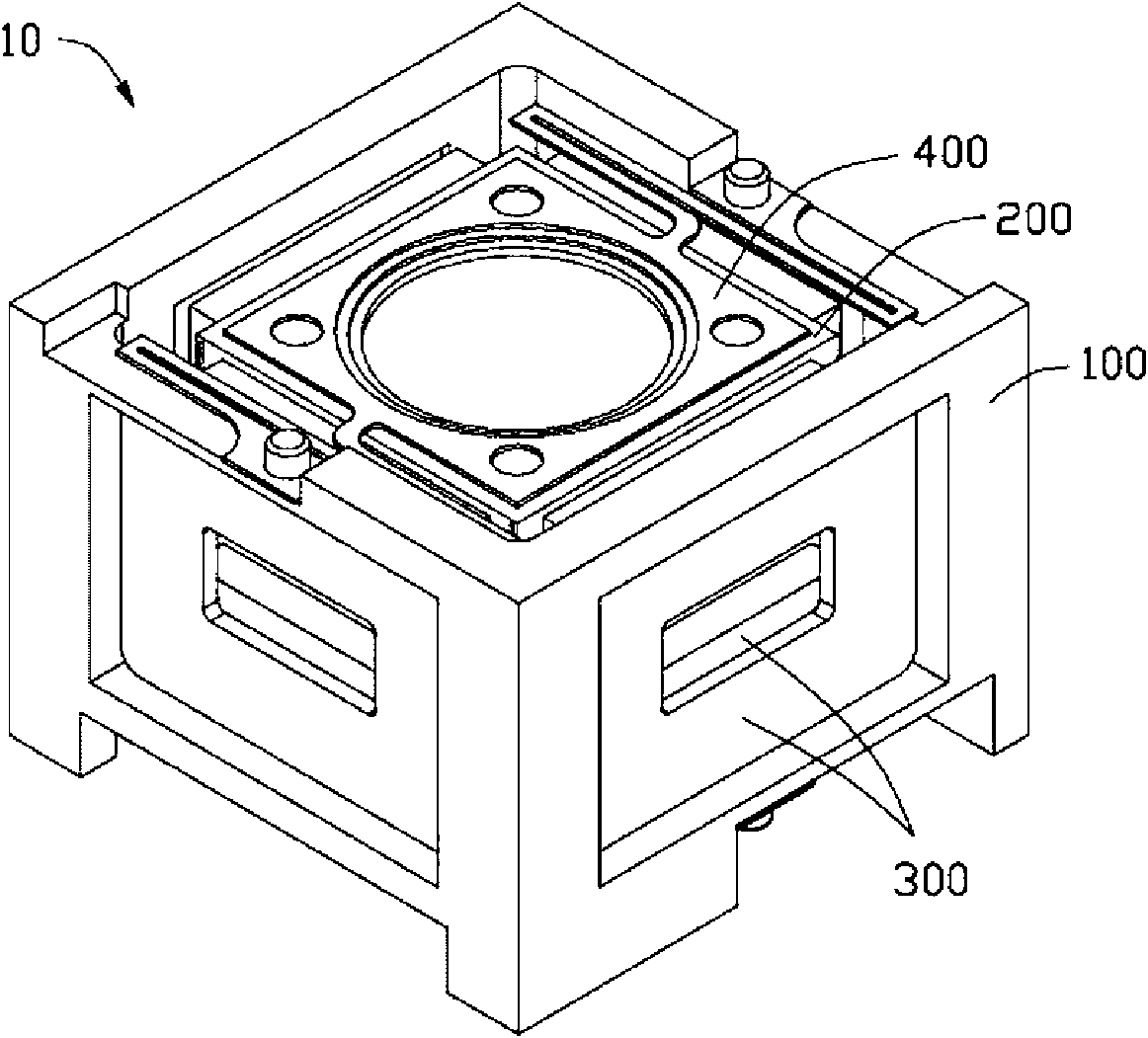
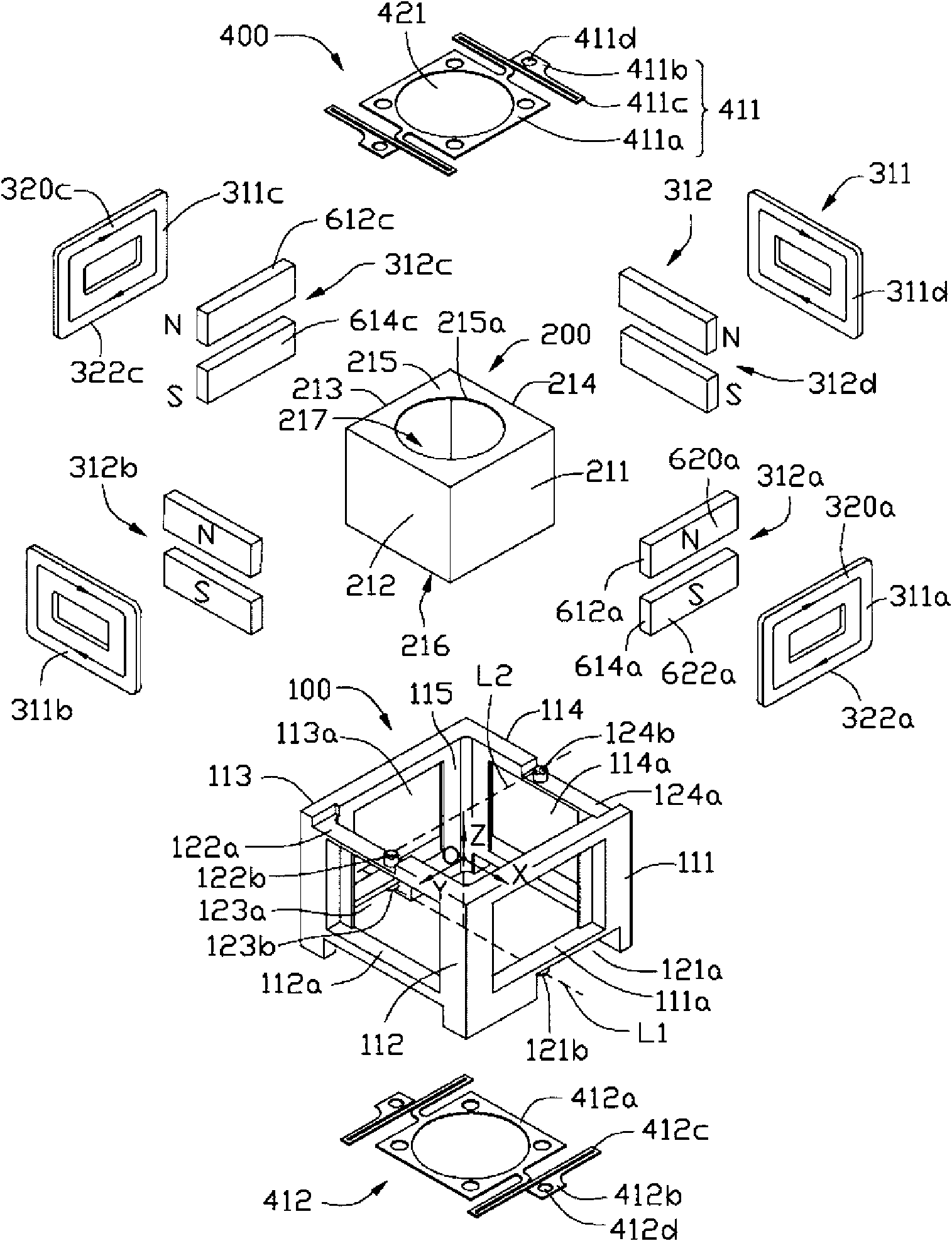
[0014] Please also refer to Figure 1 to Figure 2 , an image stabilization module 10 provided by the first embodiment of the present invention includes a fixed frame 100 , a movable frame 200 , a driving unit 300 and an elastic component 400 .

[0015] The fixing frame 100 is fixed in an electronic device, such as a digital camera (not shown). The fixing frame 100 is substantially a rectangular frame, which includes a first side wall 111 , a second side wall 112 , a third side wall 113 , and a fourth side wall 114 . The first side wall 111 , the second side wall 112 , the third side wall 113 , and the fourth side wall 114 define a first receiving space 115 . Wherein, the first side wall 111 is set opposite to the third side wall 113 , and the second side wall 112 is set opposite to the fourth side wall 114 .

[0016] The first sidewall 111 has a first rece...


PUM


Abstract

The invention relates to an image acquisition module which comprises an image stabilizing module, a lens module and an image sensor. The image stabilizing module comprises a fixed frame with a central shaft, a movable frame sharing the central shaft with the fixed frame, a driving unit and an elastic assembly. The movable frame is located within the fixed frame and separated from the fixed frame. The driving unit comprises a first magnetic assembly arranged on the fixed frame and a second magnetic assembly arranged on the movable frame. The driving unit generates a driving force through the first and second magnetic assemblies to drive the movable frame to rotate around the first axis and the second axis relative to the fixed frame respectively. The first axis is vertical to the second axis and the first and second axes are vertical to the central shaft. The elastic assembly is elastically connected between the fixed frame and the movable frame, can be used for elastically supporting the movable frame within the fixed frame and can have an elastic deformation when the movable part rotates. The movable frame is used to receive the lens module and the image sensor. The optical axis of the lens module is aligned with the image sensing module.

Description

technical field [0001] The invention relates to optical anti-shake technology, in particular to an image stabilization module capable of optical anti-shake, an image-taking module and an electronic device with the image stabilization module. Background technique [0002] The imaging module uses the shutter to control the length of time that the light is projected to the image sensor. For example, when the shutter speed is 1 / 2 second, it means that the time for the image sensor to receive light is 1 / 2 second. If the same beam of light moves on the image sensor due to shaking, the image sensor will record the movement track of the light, making the captured photo blurred. In order to compensate for the light offset caused by shaking, imaging modules that use image stabilization systems to prevent shaking began to appear in the 1990s. For details, please refer to the paper "Optical image stabilization for digital cameras" published by Cardani B. et al. in April 2006 in Control...

Claims


Application Information

Patent Timeline
Patent Type & Authority Applications(China)
IPC IPC(8): G03B5/00G03B17/00H04N5/225
CPCG03B2205/0069H04N5/23248G03B5/00G03B2205/0007H04N23/68
Inventor 丘祺纬
Owner HONG FU JIN PRECISION IND (SHENZHEN) CO LTD
Why Eureka
Try Eureka