
Power vibration absorber

A technology of dynamic vibration absorber and vibration damping rod, which is applied in the direction of metal processing machinery parts, maintenance and safety accessories, metal processing equipment, etc. It can solve the problems of unsatisfactory vibration reduction effect, non-adjustable, narrow control frequency band, etc., and achieve vibration absorption effect Good, realize the effect of automatic control and vibration reduction frequency bandwidth

Inactive Publication Date: 2012-05-30
SHAANXI UNIV OF SCI & TECH +1
View PDF0 Cites 0 Cited by
  • Summary
  • Abstract
  • Description
  • Claims
  • Application Information

AI Technical Summary

Problems solved by technology

[0002] At present, the vibration reduction methods used on vertical machining centers mainly include damper vibration reduction, bean bag vibration reduction, and pad iron vibration reduction. However, no matter which of the above vibration reduction methods, there are the following problems, that is, the control frequency band Narrow and non-adjustable; in addition, for the vertical machining center with a wide operating frequency band, the vibration reduction effect achieved by the above vibration reduction method is not ideal; and for the vibration reduction method used in the machining center for cutting vibration, there are many It is a software compensation method, which is limited by the cutting conditions and the feedback speed of the control system during use

Method used


Image

  • Power vibration absorber
  • Power vibration absorber
  • Power vibration absorber

Examples


Embodiment Construction

[0021] The dynamic vibration absorber of the present invention is described in detail below in conjunction with accompanying drawing:

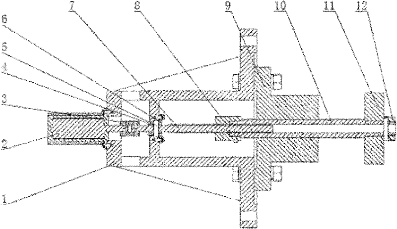
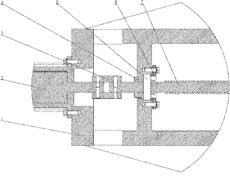
[0022] see figure 1 and combine figure 2 As shown, the dynamic vibration absorber of the present invention includes a bracket 1, a servo motor 2 fixed at one end of the bracket 1, a screw 7 fixedly connected to the servo motor 2 through a coupling 3, a transmission nut 8 connected to the screw 7 through threads, and a transmission The damping rod 10 fixedly connected to the nut 8, the damping seat 9 fixedly connected to the bracket 1 and opposite to the servo motor 2, and the mass block 11 fixed on the other end of the damping rod 10 and opposite to the drive nut 8, the The other end of the mass block 11 is fixed on the damping rod 10 by a nut 12 .

[0023] Please see in particular figure 2 As shown in Figure 5, the servo motor 2 is fixed on the bracket 1 by screws; the bracket 1 is provided with a bearing seat, and the deep groove ball b...


PUM


Abstract

The invention provides a power vibration absorber comprising a support frame (1), a servo motor (2), a screw rod (7), a transmission nut (8), a vibration reducing rod (10), a vibration reducing seat (9) and a mass block (11), wherein the servo motor (2) is fixed at one end of the support frame (1); the screw rod (7) is driven by the servo motor (2); the transmission nut (8) is in thread engagement with the screw rod (7); the vibration reducing rod (10) is fixedly connected with the transmission nut (8); the vibration reducing seat (9) is fixedly connected with the support frame (1) and penetrated by the vibration reducing rod (10); and the mass block (11) is fixed on the vibration reducing rod (10) and arranged opposite to the support frame (1). The natural frequency of the power vibration absorber can be regulated through a motor, therefore needed vibration reducing bandwidth can be achieved through less vibration absorption mass; and in addition, the invention has simple structure and higher system reliability.

Description

technical field [0001] The invention relates to a vibration absorber, in particular to a dynamic vibration absorber. Background technique [0002] At present, the vibration reduction methods used on vertical machining centers mainly include damper vibration reduction, bean bag vibration reduction, and pad iron vibration reduction. However, no matter which of the above vibration reduction methods, there are the following problems, that is, the control frequency band Narrow and non-adjustable; in addition, for the vertical machining center with a wide operating frequency band, the vibration reduction effect achieved by the above vibration reduction method is not ideal; and for the vibration reduction method used in the machining center for cutting vibration, there are many It is a software compensation method, which is limited by the cutting conditions and the feedback speed of the control system during use. Contents of the invention [0003] The technical problem to be sol...

Claims


Application Information

Patent Timeline
Patent Type & Authority Patents(China)
IPC IPC(8): B23Q11/00
Inventor 张功学徐金华曹巨江张宁宁张淳刘超峰李宁
Owner SHAANXI UNIV OF SCI & TECH
Learn More