Cutting machine

A cutting machine and release mechanism technology, applied in metal sawing equipment, sawing machine devices, metal processing equipment, etc., can solve problems such as damage and achieve the effect of avoiding damage

Inactive Publication Date: 2011-04-06
POSITEC POWER TOOLS (SUZHOU) CO LTD
View PDF0 Cites 6 Cited by
  • Summary
  • Abstract
  • Description
  • Claims
  • Application Information

AI Technical Summary

Problems solved by technology

During this process, if the operator accidentally touches the saw blade, it will cause unnecessary injury

Method used


Image

  • Cutting machine
  • Cutting machine
  • Cutting machine

Examples


Embodiment Construction

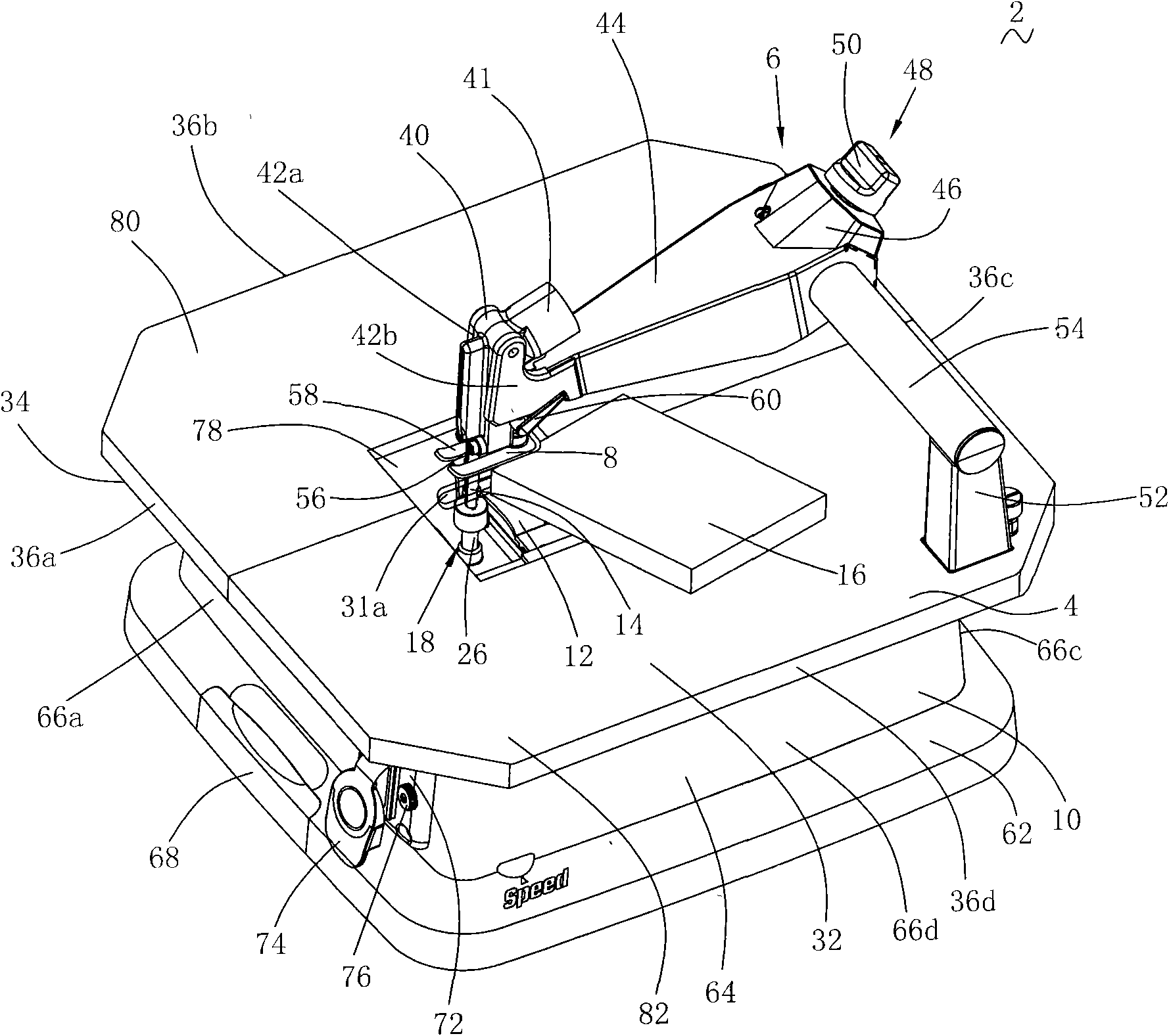
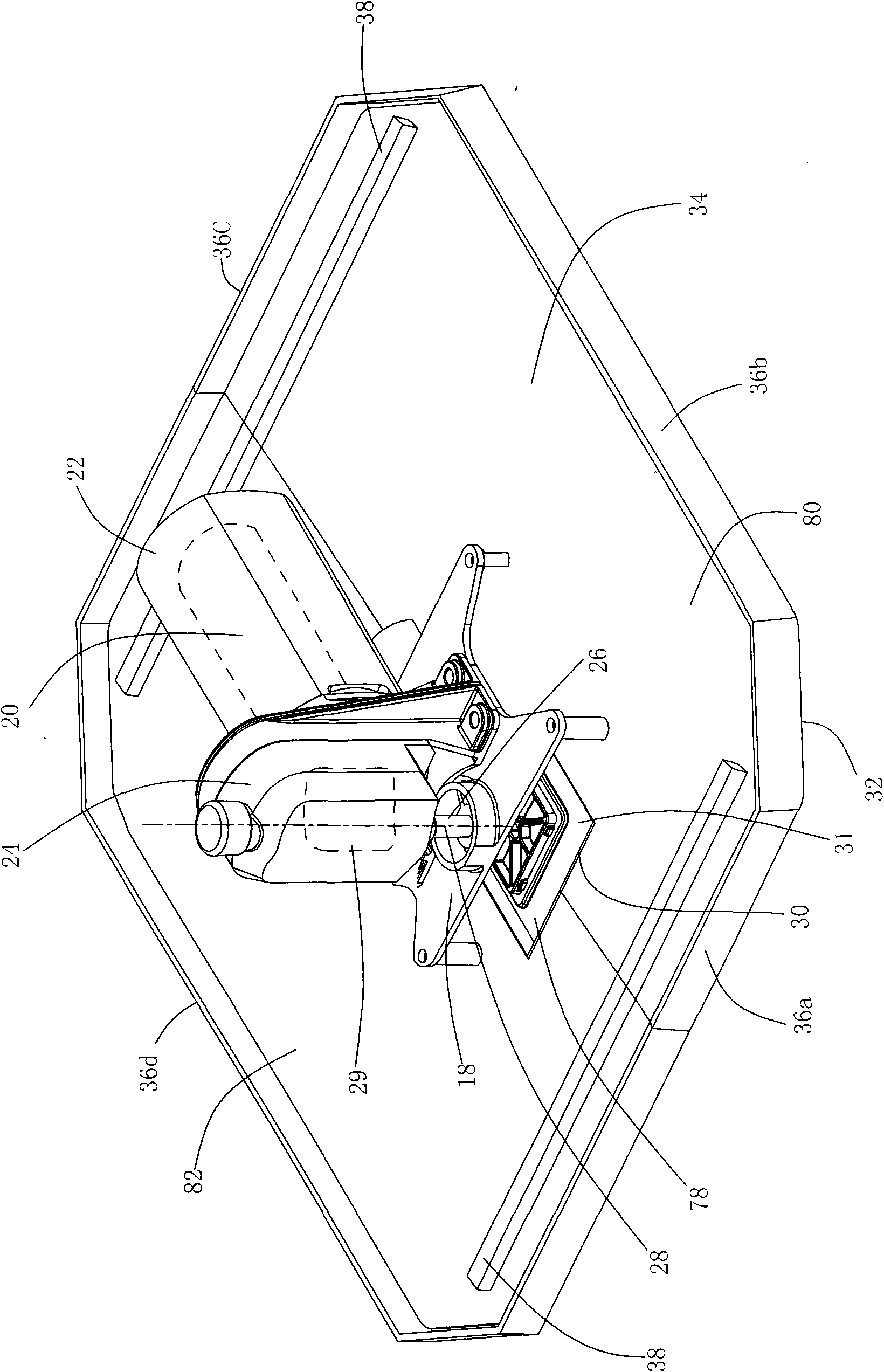
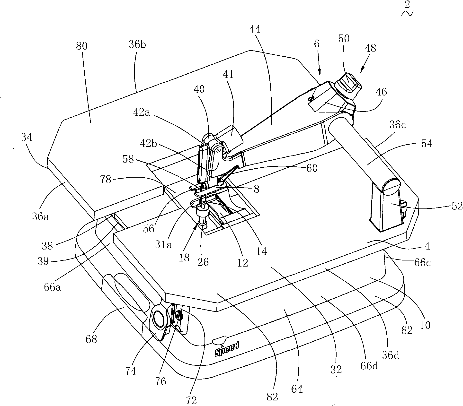
[0038] See attached Figure 1-2 , a cutting machine 2, comprising a workbench 4, a support 10 supporting the workbench 4, a shield assembly 6 arranged on the upper surface 22 of the workbench 4, connected with the shield assembly 6 and adjustable to apply a certain pressure to the workpiece The platen assembly 8 and the cutting mechanism 12 arranged on the lower surface 24 of the workbench 4 .

[0039] According to the operator's usual way of using this type of cutting machine, define figure 1 The middle left is the front part of the cutting machine 2, and the right side is the rear part of the cutting machine 2. The table 4 has an upper surface 32, a lower surface 34, and side walls 36a, 36b, 36c, 36d extending vertically relative to the upper and lower surfaces. The opening 30 is opened on the workbench 4 , located at the front of the cutting machine 2 , and penetrates from the upper surface 32 to the lower surface 34 . The saw blade 14 passes through the opening 30 from ...


PUM


Abstract

The invention relates to a cutting machine, which comprises a workbench, a support, a cutting mechanism and a saw blade clamping / releasing mechanism, wherein the workbench is provided with an opening, and comprises an upper surface for supporting workpieces; the support is used for supporting the workbench; the cutting mechanism is fixed on the lower surface of the workbench and accommodated in the support, and comprises a motor for outputting rotary motion, a reciprocating lever for driving a saw blade passing through the opening to carry out reciprocating motion, and a motion conversion mechanism for converting the rotary drive of the motor into the reciprocating motion of the reciprocating lever; the saw blade clamping / releasing mechanism is used for clamping and releasing the saw blade; and the workbench is provided with at least part of transparent portion, and the saw blade clamping / releasing mechanism is arranged below the transparent portion. When the operator replaces the saw blade, the damage on hands caused by incorrect operation is avoided.

Description

technical field [0001] The invention relates to a cutting machine, in particular to a cutting machine with a reciprocating cutting mechanism. Background technique [0002] Existing jigsaws can perform various curved and straight cuts, and are therefore widely used in processing boards of various materials. Generally, a jigsaw includes a motor, a housing housing the motor, a motion conversion mechanism housed in the gear box housing, driven by the motor and converting the rotational motion of the motor into the reciprocating motion of the reciprocating rod, and connected to the reciprocating rod through a chuck device The saw blade, and the bottom plate that supports the body of the jigsaw on the surface of the workpiece. [0003] In order to expand the application of the jigsaw, technicians in the industry place it upside down on the lower surface of a workbench, so that the cutting process can be performed when the workpiece needs to be moved. However, the existing invert...

Claims


Application Information

Patent Timeline
IPC IPC(8): B23D51/02
Inventor 何明明
Owner POSITEC POWER TOOLS (SUZHOU) CO LTD
Why Eureka
Try Eureka