
Retention needle tube assembly

A technology for indwelling needles and catheter components, which is applied in the direction of needles, guide needles, and instruments introduced into the body, and can solve the problems of needle point puncture, needle point piercing of blood vessels, needle point scratching of vascular intima, etc., to avoid vasculitis , high success rate of operation, avoiding injury and the painful effect of needing to puncture again

Active Publication Date: 2011-04-06
FUJIAN BESTWAY MEDICAL POLYMER CORPORATION
View PDF6 Cites 4 Cited by
  • Summary
  • Abstract
  • Description
  • Claims
  • Application Information

AI Technical Summary

Problems solved by technology

[0003] The disadvantages of the above indwelling needles are: 1. After the puncture, the protective sheath needs to be fully stretched to include the puncture needle tube in its protective sheath. When fully stretched, the catheter assembly is withdrawn, resulting in the puncture needle tip still being exposed, at this time the protective cover loses its containment effect on the needle tube, prone to needle tip injury accidents, resulting in medical problems
2. After the puncture needle tube is punctured, the needle tip is still exposed outside the catheter port and is sent into the deep blood vessel together with the catheter. If the operation is not done properly, or the blood vessel condition is not good, the needle tip can easily scratch the intima of the blood vessel, causing vasculitis ;During the delivery of the tube, the needle tip may puncture the blood vessel again, resulting in the failure of the tube placement, causing the patient to suffer pain and the pain of re-puncture

Method used


Image

  • Retention needle tube assembly
  • Retention needle tube assembly
  • Retention needle tube assembly

Examples


Embodiment Construction

[0038] Best practice:

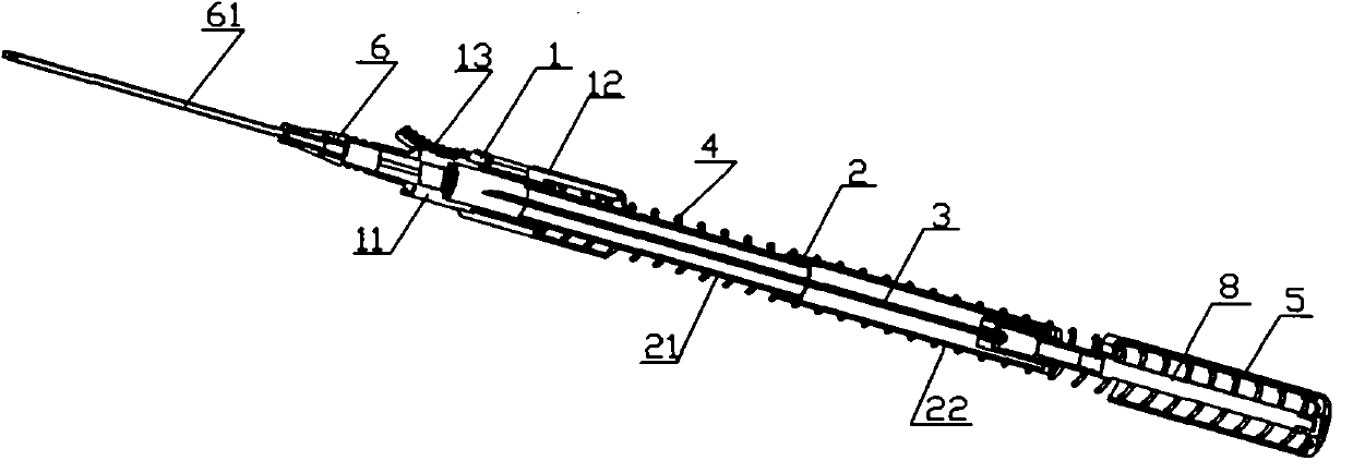
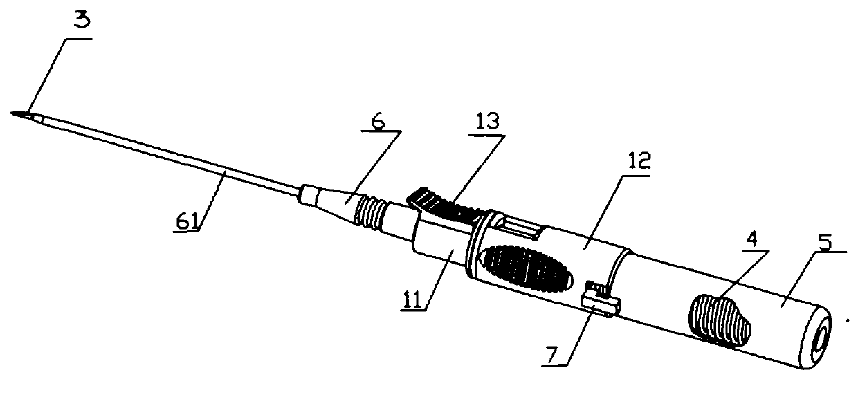
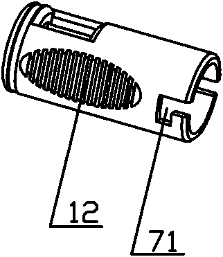
[0039] Refer to attached figure 1 , the indwelling needle and needle tube assembly, including a connecting member 1, a telescopic protective sleeve 2, a needle tube 3, an extension spring 4, and a needle holder 5; the connecting member 1 includes a connecting sleeve 11 and a handle 12, and the telescopic protective sleeve 2 includes a small slide bar 21 And a large slide bar 22; the needle tube 3 is installed in the needle holder 5 through a connecting rod 8.

[0040] in the attached figure 1 on the basis of referring to the attached Figure 5, the inner cavity of the connecting sleeve 11 is in the shape of a step from the front end to the rear end, followed by the needle lumen, the isolation cavity and the inner cavity, the outer shape of the needle lumen is a boss 111, and the isolation cavity 112 is an inverted The tapered cavity is filled with an isolation plug 114, the inner cavity 113 is a cylindrical cavity, and the three cavities are distribu...


PUM


Abstract

The invention relates to an instrument for introducing medium into bodies, particularly a retention needle tube assembly which comprises a connecting component, a retractable protective sleeve, a needle stand and a needle tube. The retention needle tube assembly is structurally characterized by also comprising an extension spring, wherein the retractable protective sleeve is enclosed in the innercavity of the needle stand after being compressed; and the connecting component, is connected with the needle stand through a buckling device. The invention has the technical characteristics that theextension spring is arranged in the retention pin with the retractable protective sleeve; and in the piercing process, the needle stand and the retractable protective sleeve are unfolded under the action of the spring, the needle tube retreats from the guide tube along with the needle stand and finally leaves the guide tube assembly to enter the retractable protective sleeve, and meanwhile, the connecting component, is held by a hand so as to feed the guide tube into deep inside vessels. In the piercing process, the needle point is no longer exposed outside the port of the guide tube, so thatthe needle point can not hurt the vessel when feeding the tube, thereby preventing angitis from generation. As for the medical care operators, the operation success rate is high; and as for the patients, injury and pain from piercing again can be prevented.

Description

technical field [0001] The invention relates to a device for introducing a medium into the body, in particular to an indwelling needle tube assembly. Background technique [0002] In the prior art, there is an indwelling needle with a retractable protective sheath that can prevent stab wounds. For details, please refer to Chinese patent ZL200920139686.7. This kind of indwelling needle includes a catheter assembly and a needle tube assembly. The catheter assembly includes a flexible catheter, a catheter hub connected to one end of the catheter, and a handle connected to the catheter hub. Protective sheath and hub with rigid puncture needle. Before use, the puncture needle tube is inserted into the catheter, and the needle tip is exposed, and the protective sleeve is in a compressed state, and is movably connected with the catheter base. When in use, first puncture the puncture needle tube with the catheter into the blood vessel through one-handed operation, and apply force ...

Claims


Application Information

Patent Timeline
IPC IPC(8): A61M5/158A61M25/06
Inventor 陈永曦
Owner FUJIAN BESTWAY MEDICAL POLYMER CORPORATION
Learn More