
Clock generating circuit

A technology of clock generation circuit and gating circuit, which is applied in the direction of electric pulse generation, electric pulse generator circuit, pulse generation, etc., can solve the problems of complex ring oscillator design, limited clock frequency accuracy, and high technical difficulty, and achieve The effect of small process deviation, simple structure and elimination of influencing factors

Inactive Publication Date: 2011-03-30
CHENGDU MINGXINGXINGTONG TECH CO LTD
View PDF4 Cites 7 Cited by
  • Summary
  • Abstract
  • Description
  • Claims
  • Application Information

AI Technical Summary

Problems solved by technology

However, the design of the ring oscillator with compensation for process, voltage, temperature, etc. is more complicated, and the technical difficulty is relatively large. The design of the RC oscillator is simple, but the accuracy of the clock frequency is limited due to the process deviation of the resistance and capacitance.

Method used


Image

  • Clock generating circuit
  • Clock generating circuit
  • Clock generating circuit

Examples


Embodiment Construction

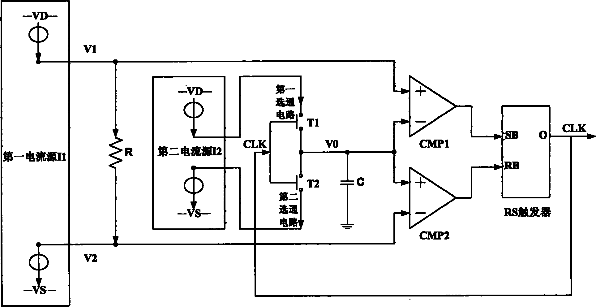
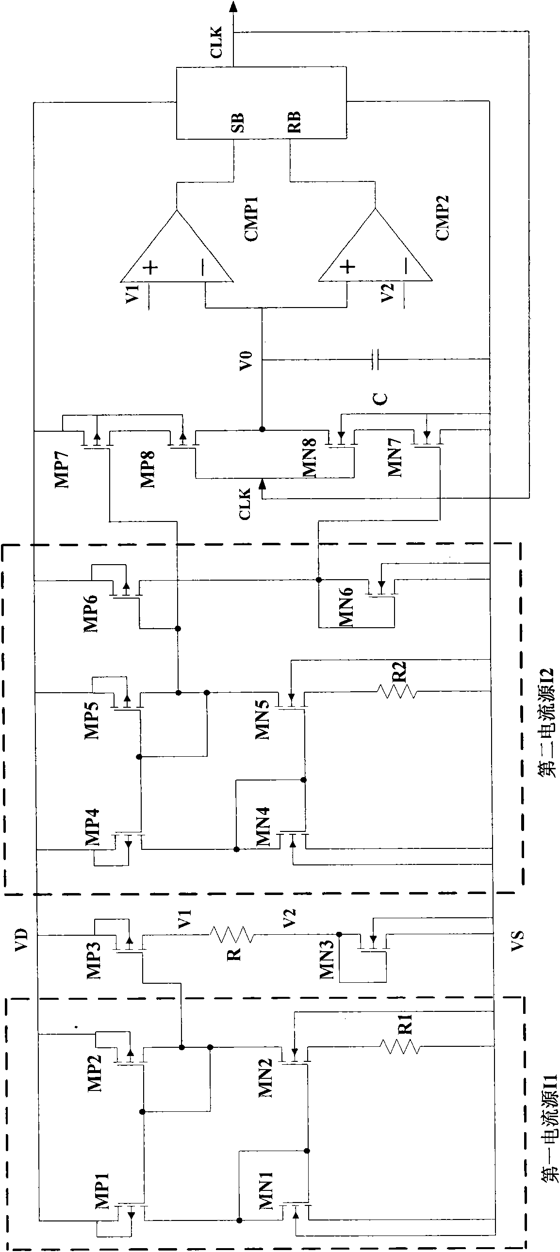
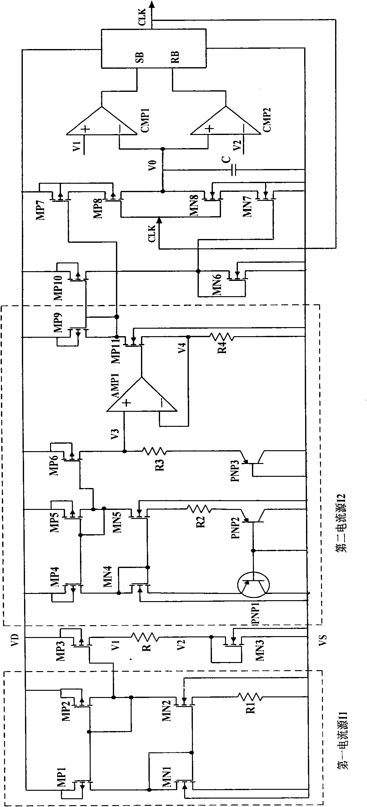
[0010] See figure 1 The preferred embodiment of the clock generation circuit of the present invention includes a first current source I1, a second current source I2, a resistor R connected to the first current source I1, a capacitor C, and a second current source connected to the capacitor C. A comparator CMP1, a second comparator CMP2 connected to the capacitor C, an RS flip-flop connected to the first comparator CMP1 and the second comparator CMP2, and a first comparator connected to the second current source I2 A strobe circuit and a second strobe circuit. In this embodiment, the first current source I1 and Proportionally, it includes a first power terminal and a first ground terminal, assuming The second current source I2 and Proportionally, it includes a second power terminal and a second ground terminal, assuming The first power terminal and the second power terminal are both connected to a power terminal VD, the first ground terminal and the second ground terminal are...


PUM


Abstract

The invention discloses a clock generating circuit. The clock generating circuit comprises a first current source, a resistor connected with the first current source, a second current source, a first gating circuit connected with the second current source, a second gating circuit connected with the second current source, a capacitor connected with the first gating circuit and the second gating circuit, a first comparator connected with the first current source and the capacitor, a second comparator connected with the first current source and the capacitor, and a remote sensing (RS) trigger connected with the first comparator and the second comparator, wherein the RS trigger outputs a clock signal to an input control terminal of the first gating circuit and an input control terminal of thesecond gating circuit; when the first gating circuit is gated, the second current source charges the capacitor; and when the second gating circuit is gated, the second current source discharges the capacitor. The clock generating circuit has a simple structure, low process variation and relatively low cost and improves the clock precision to the maximum degree.

Description

Technical field [0001] The invention relates to an integrated circuit, especially a clock generating circuit. Background technique [0002] The clock generation circuit is an important part of integrated circuit design. Usually an off-chip crystal or crystal oscillator is used to provide a precise clock source, but this increases the system cost, so it is necessary to design an accurate on-chip clock generation circuit. [0003] In the traditional on-chip clock generation circuit, ring oscillators with compensation for process, voltage, temperature, etc. are mostly used, or RC oscillators are used. However, the design of a ring oscillator with compensation for process, voltage, temperature, etc. is more complicated and technically difficult. The design of an RC oscillator is simple, but the accuracy of the clock frequency is limited due to the influence of the process deviation of resistance and capacitance. Summary of the invention [0004] In view of the above, it is necessary to...

Claims


Application Information

Patent Timeline
Patent Type & Authority Applications(China)
IPC IPC(8): H03K3/02H03K3/011
CPCH03K4/501
Inventor 吴召雷吕亚兰武国胜
Owner CHENGDU MINGXINGXINGTONG TECH CO LTD
Learn More