Eureka AIR delivers breakthrough ideas for toughest innovation challenges, trusted by R&D personnel around the world.

Optical path autocorrelator for distributed optical fiber strain sensing measurement

A distributed optical fiber and optical fiber sensor technology, applied in the field of optical fiber, can solve the problems of increasing stability, deteriorating measurement accuracy, and low utilization rate, and achieve the effect of increasing utilization efficiency and suppressing degradation

Inactive Publication Date: 2012-06-06
HARBIN ENG UNIV
View PDF8 Cites 0 Cited by
  • Summary
  • Abstract
  • Description
  • Claims
  • Application Information

AI Technical Summary

Problems solved by technology

[0007] The purpose of the present invention is to provide a real-time monitoring and measurement of physical quantities such as multi-point strain or deformation, which solves the problem of excessive light source power loss, low utilization rate and low light source feedback when multiple sensors are multiplexed in one optical fiber. The problem of measurement accuracy degradation caused by light, the optical path autocorrelator used for distributed optical fiber strain sensing measurement to increase the stability of the system

Method used


Image

  • Optical path autocorrelator for distributed optical fiber strain sensing measurement
  • Optical path autocorrelator for distributed optical fiber strain sensing measurement
  • Optical path autocorrelator for distributed optical fiber strain sensing measurement

Examples


Embodiment Construction

[0054] The present invention is described in more detail below in conjunction with accompanying drawing example:

[0055] A scheme for distributed optical fiber strain sensing measurement system based on annular multi-beam generator, such as Figure 5 shown. Depend on Figure 5 It can be seen that the distributed optical fiber white light interference sensor array is composed of a wide-spectrum light source 1, an annular multi-beam generator 2, an optical path autocorrelation detection unit 3, a transmission optical fiber 4, and an optical fiber sensor array 5 connected in sequence from end to end. The annular multi-beam generator 2 is composed of a 2×2 fiber coupler 21, a three-port optical circulator 22, a fiber collimator 23, and a movable optical mirror 24; the optical path autocorrelation detection unit 3 is composed of a three-port optical circulator 31 , a light detector 32 and an interference signal detection and processing unit 33.

[0056] Such as Figure 5 shown...


PUM


Abstract

The invention provides an optical path autocorrelator for distributed optical fiber strain sensing measurement, which is formed by sequentially connecting a broad spectrum light source (1), an annular multibeam generator (2), an optical path autocorrelation detecting unit (3), a transmission optical fiber (4) and an optical fiber sensor array (5) end to end; the annular multibeam generator (2) comprises a 2*2 optical fiber coupler (21), a first three-port optical circulator (22), an optical fiber collimator (23) and a movable optical reflector (24); and the optical path autocorrelation detecting unit (3) comprises a second three-port optical circulator (31), an optical detector (32) and an interference signal detecting and processing unit (33). The invention can realize real-time monitoring and measurement of physical quantities, such as multi-point strain or deformation, and the like,solve the problems of overlarge light source power loss and superlow light source utilization ratio when a plurality of sensors are multiplexed in an optical fiber and the problem of measurement precision reduction caused by the existence of light source feedback light and improve the stability of a system.

Description

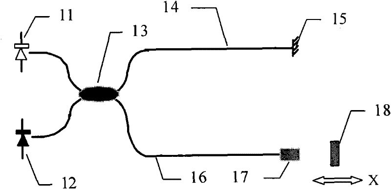
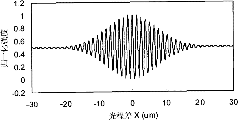
technical field [0001] The invention belongs to the field of optical fiber technology, and in particular relates to an optical path autocorrelator for distributed optical fiber strain sensing measurement. Background technique [0002] Fiber-optic interferometers driven by low-coherence, broadband light sources such as light-emitting diodes (LEDs), superspontaneous emission sources (ASEs) or superluminescent laser diodes (SLDs) are often referred to as white-light fiber interferometers. The structure of a typical fiber optic white light interferometer is as follows: figure 1 As shown, the Michelson-type interferometer built by single-mode optical fiber uses a wide-spectrum light source LED or ASE as the light source, and realizes the measurement of the physical quantity to be measured through the white light interference fringes detected by the detector. Its working principle is as follows, after the broadband light emitted by the low-coherence broadband light source 11 ente...

Claims


Application Information

Patent Timeline
Patent Type & Authority Patents(China)
IPC IPC(8): G01B11/16
Inventor 苑勇贵杨军苑立波
Owner HARBIN ENG UNIV
Why Eureka
Eureka Blog
Learn More