Compound underflow constructed wetland system

A constructed wetland system and wetland technology, which is applied in the field of compound subsurface constructed wetland system, can solve the problems of low biological nitrification and denitrification efficiency, unsatisfactory total nitrogen removal effect, and shortened wetland service life, etc. The effect of enhancing denitrification capacity and saving project expenses

Inactive Publication Date: 2012-03-14
天津市天水环保设计工程有限公司
View PDF0 Cites 0 Cited by
  • Summary
  • Abstract
  • Description
  • Claims
  • Application Information

AI Technical Summary

Problems solved by technology

[0003] Subsurface flow constructed wetlands have been widely used at home and abroad because of their low investment and operation costs, good effluent quality, and easy maintenance. Degraded macromolecular organic matter and suspended matter accumulate for a long time and block, reducing the service life of the wetland; (2) The efficiency of biological nitrification and denitrification in the wetland is relatively low, and the removal effect of total nitrogen is not ideal; (3) Low temperature operation in winter The treatment effect is poor; (4) limited by the ability of plant roots to transmit oxygen, wetlands are generally shallow and occupy a large area

Method used


Image

  • Compound underflow constructed wetland system
  • Compound underflow constructed wetland system
  • Compound underflow constructed wetland system

Examples


Embodiment Construction

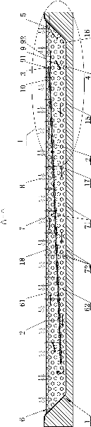
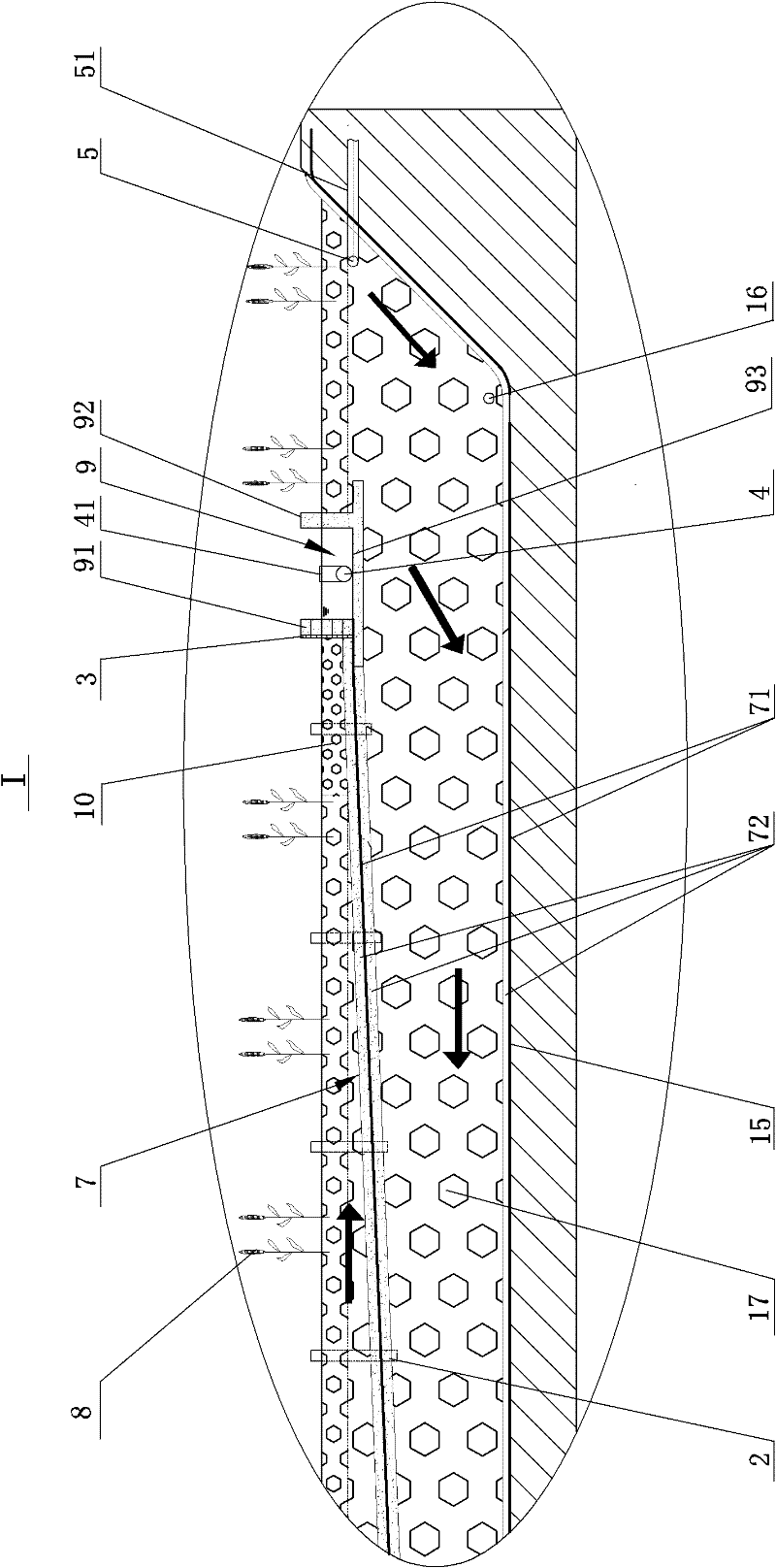
[0022] Figure 1-Figure 5 It shows a compound subsurface flow constructed wetland system, including a rectangular wetland pool 1 and a wetland bed 6 filled in the pool body. The above-mentioned wetland pool is composed of long side dams 11, 12 and short side dams 13, 14 surrounding the ground. The wetland pool It is the external support body of the whole wetland system, and its upper surface is paved with a geomembrane 71 for waterproofing. The surface of the geomembrane 71 is provided with a protective layer 72. The protective layer is a finely divided filler layer with a particle size of 5-10mm. The thickness of the finely divided filler layer is in accordance with the civil engineering industry. Sure. The surface layer of the above-mentioned wetland bed body 6 is a small particle diameter filler layer 61 , and the surface layer to the pool bottom 15 is a large particle diameter filler layer 62 . Small particle size, large particle size filler and finely crushed filler gene...


PUM

PropertyMeasurementUnit
particle diameteraaaaaaaaaa
thicknessaaaaaaaaaa
particle diameteraaaaaaaaaa

Abstract

The invention relates to a compound underflow constructed wetland system, comprising a wetland pool and a wetland bed body. The surface layer of the wetland bed body is covered with small size filler layers. Big size filler layers are arranged from the surface layer to the pool bottom. The wetland bed body is provided with a water inlet pipe and a water collecting tank. The water collecting side of the water collecting tank is a water collecting tracery wall to connect a fine grid, and a water outlet pipe is arranged in the water collecting tank. Wetland plants are distributed on the surface of the wetland bed body. The system is characterized in that a water inlet end and a water outlet end are arranged on the same end of the wetland bed body; the water inlet pipe is a perforated pipe horizontally arranged between the big size filler layers and the small size filler layers along the direction of a short side dam; the water collecting tank and the water inlet pipe are arranged on one side of the water inlet pipe far from the short side dam; a waterproof layer is arranged at the lower inclined part of the wetland bed body along a long side dam; the upper end of the waterproof layeris connected with the bottom of the water collecting tracery wall; the lower end and the back end short side dam and the pool bottom keep a distance; long sides on the two sides are connected with the dam; and the wetland bed body is provided with a gas relief pipe. The system has the advantages that the removal of total nitrogen is improved, the wetland blockage is delayed, the occupation area is reduced, and the high treatment efficiency is realized during operation at a low temperature or in winter.

Description

technical field [0001] The invention relates to a sewage and waste water treatment facility, in particular to a compound subsurface flow artificial wetland system. Background technique [0002] Constructed wetland system water purification technology is a new type of sewage and wastewater treatment technology developed in the 1970s and 1980s. Constructed wetlands are artificial ecosystems that simulate natural wetlands. In depressions with a certain aspect ratio, soil, sand, gravel and other matrix fillers are mixed to form a filler bed, and plants such as reeds and Chinese cabbage have good treatment performance on the bed. The sewage and wastewater treatment system formed by aquatic plants with long growth cycle, beautiful appearance and economic value has the functions of water treatment and restoration of natural ecology. When the sewage and waste water pass through the system, the water body flows in the filler of the bed body, the plant rhizosphere gap or the surface ...

Claims


Application Information

Patent Timeline
Patent Type & Authority Patents(China)
IPC IPC(8): C02F3/32C02F3/34C02F3/30
CPCY02W10/10
Inventor 居文钟李士荣孙贻超李永健刘永贾晓玉李然张悦杨健邓小文卢学强苏志龙
Owner 天津市天水环保设计工程有限公司
Why Eureka
Try Eureka