Blasting chamber
A technology of sandblasting room and main unit, which is applied in the field of sandblasting room or working room, and can solve problems such as working room which have not yet been raised
- Summary
- Abstract
- Description
- Claims
- Application Information
AI Technical Summary
Problems solved by technology
Method used
Image
Examples
no. 1 example
[0075]overall structure
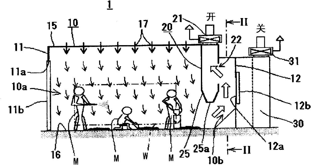
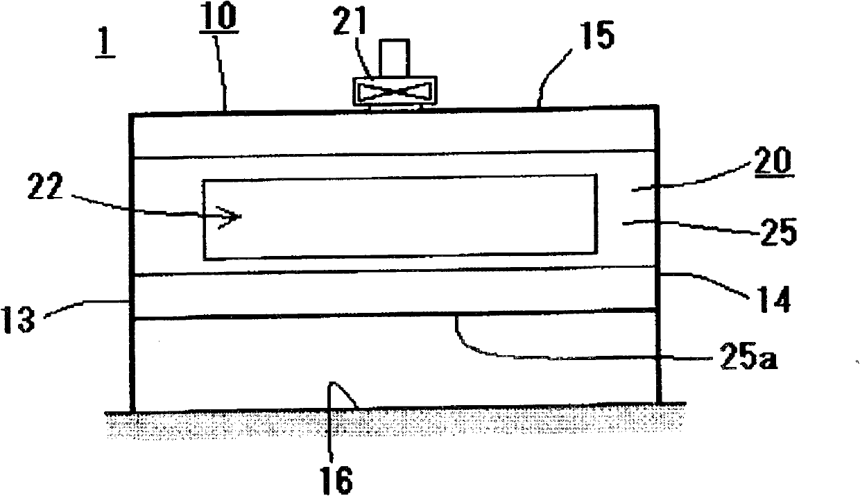
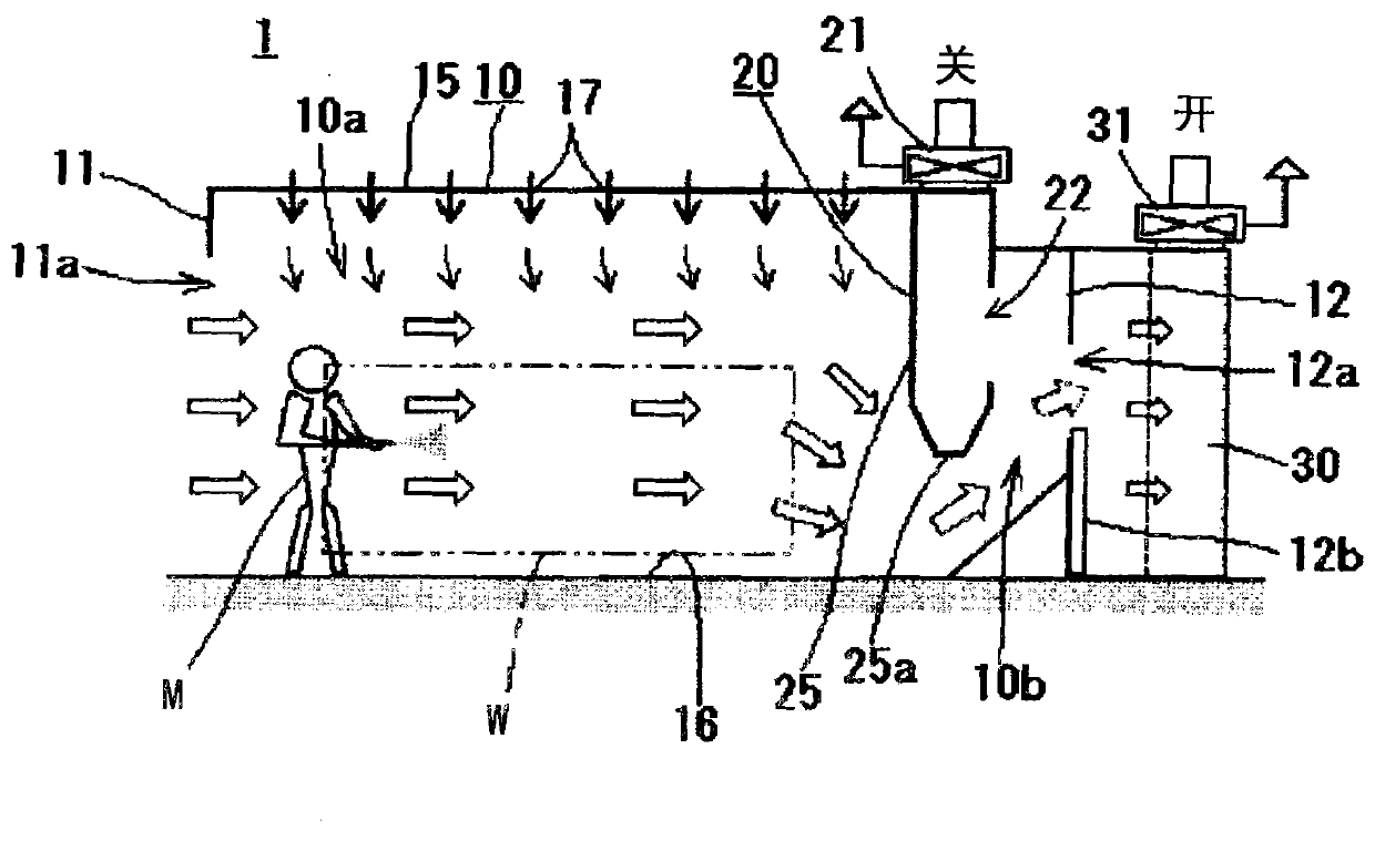
[0076] Figure 1 to Figure 3 The reference numeral 1 in is the sandblasting chamber of the present invention. Such as figure 1 and figure 2 As shown, although its overall shape is not particularly limited, this working room 1 is manufactured so that a worker M can enter and work with a workpiece W, and the working room 1 is equipped with side walls 11 to 14, a top plate 15, and a bottom plate 16. The surrounded substantially box-shaped main unit 10; the dust collecting unit 20 which ventilates the main unit 10 during the blasting process; and the ventilation unit 30 which ventilates the main unit 10 during painting.
[0077] main unit
[0078] The above-mentioned main unit 10 constituting the working chamber 1 of the present invention is a box-shaped chamber made of, for example, metal and formed by two pairs of opposite side walls ( 11 and 12 and 13 and 14 ), a top plate 15 and a bottom plate 16 . This main unit 10 is formed with a work space 1...
no. 2 example
[0131] Another embodiment construction (second specific example) of working chamber 1 of the present invention will refer to Figures 5 to 7 to describe.
[0132] Figures 5 to 7 The working chamber 1 of this particular example shown in is provided with a collection unit 40 constructed from a collection duct 41 , a cyclone 42 and an exhaust duct 43 . The Studio 1 with the above reference Figures 1 to 4 The working chamber 1 of the first embodiment described above is different in that a second opening / closing member 44 and a third opening / closing member 45 are provided in the ventilation duct 10b. Other constructions and references Figures 1 to 4 The working chambers 1 of the first specific example described are the same, and therefore, description of common parts will be omitted.
[0133] The cyclone 42 constituting the above-mentioned collection unit 40 generates a vortex flow therein by the airflow passing through the inside, thereby collecting the abrasives having a r...
no. 3 example
[0153] As mentioned above, in reference to Figures 5 to 7 In the second specific example described above, although the dust collection unit 20 makes the working space 10a ventilate through the ventilation duct 10b and collects the abrasives through the collection unit 40 alternately, the collection of abrasives from the working space 10a can be combined with the above-mentioned dust collection unit 20. Ventilation of the working space 10a is performed simultaneously.
[0154] As a third specific example, refer to Figure 8 and Figure 9 An example configuration of the working chamber 1 configured in this way is described.
[0155] exist Figure 8 and Figure 9 In the specific example described in, in addition to the collection duct 41 ', cyclone 42 ' and exhaust duct 43 ', the collection unit 40' also has a dust collector 50 equipped with an exhaust fan 51, and the exhaust duct 43 ' communicate with the inlet of this dust collector 50.
[0156] By placing porous plates ...
PUM
 Abstract
Description
Claims
Application Information
 - R&D
- Intellectual Property
- Life Sciences
- Materials
- Tech Scout
- Unparalleled Data Quality
- Higher Quality Content
- 60% Fewer Hallucinations
Browse by: Latest US Patents, China's latest patents, Technical Efficacy Thesaurus, Application Domain, Technology Topic, Popular Technical Reports.
© 2025 PatSnap. All rights reserved.Legal|Privacy policy|Modern Slavery Act Transparency Statement|Sitemap|About US| Contact US: help@patsnap.com


